Forget Crazy Earth,
Look to the Future:
Voyager and Fortran 5
Early 2024
(Updated: 18-Jul-2025)
The Voyager spacecraft,
Voyager 1 and
Voyager 2, were
not programmed in Fortran 5. Or in any
Fortran for that matter. This widely accepted misbelief can be traced back
to a widely misunderstood statement in a single magazine article.
This is a personal project of mine. Everywhere I turned the past few
years, someone was saying that the Voyager spacecraft were programmed
in Fortran 5. I didn't believe it. I gathered a few links here and
there, but, in early 2024, I sat down and did some serious online
research. Well, kind of serious and not particularly systematic.
This is what I found. It's wordy, it rambles, and the writing is
somewhat uneven, but I hope you'll find the information useful or
at least follow the links in your own explorations. There are many
fascinating aspects of the Voyager project that one normally might
not think of and only learn of by accident. I think you'll find
that even casual browsing can yield rich rewards!
Sections 1 through 5, about 10 printed pages, are specifically about the
Voyager-Fortran 5 meme. Section 6 adds another 9 pages and seeks to
prevent memes such as this from arising. The remaining tens of pages began
as simply a source of more detailed information about things presented in
the earlier sections, things such as command sequencing and the AACS
computer. However, I gradually added more unrelated information such as
the flight computer electronics because (i) the information was interesting
and, as a justification in hindsight, (ii) collecting this information in
one place will save other Voyager tech fans the effort of, for example,
tracking down and connecting nuggets from obscure posts in lengthy online
discussions.
You'll find phrases like "apparently", "perhaps", "it seems", and
"it suggests" throughout the text. They mean I can't definitively
assert what the sentence is about to say. For example, a great deal
of my discussion of sequencing and simulation is based on McEvoy's
Viking Orbiter paper. There is no comparable Voyager paper that
provides his level of detail, so I can't with certainty say that
something done on Viking is done in the same way on Voyager—it
just seems likely! These uncertainties do not affect the
fact — and central thrust of this piece — that
the Voyager onboard computers were not programmed in Fortran.
My background: I'm a retired software developer. In the 1980s, I worked
on the image processing ground system for NASA's LANDSAT 4 and 5 remote
sensing satellites; we used VAX/VMS Fortran 77. In the late 1980s and
early 1990s, I worked on a configurable, Unix workstation-based, control
center for NASA's Goddard Space Flight Center, mostly written in C. In
the late 1990s through the mid-2000s, I worked on a similar system in C++
for commercial satellite fleets. (The latter was originally based on the
former thanks to NASA's generosity in sharing technology with industry.)
My brother, Andy, got interested in ham radio when we were in junior high
school and I picked up a rudimentary knowledge of electronics and radio
through osmosis. (Andy has an Extra Class license; originally WA3RML
from Maryland, he's now WA5RML in Texas.)
Acknowledgements: The bulk of this page was written in early 2024.
In the swirl of useful and not-useful papers and articles I read or skimmed,
bouncing here and there on the web, I generally didn't remember how I came
across individual sources and therefore I was unable to properly credit
people through whom I found many of these sources. Later in the year, I
began being more meticulous about recording the sources of the sources in
my (disorganized) offline notes and then crediting them on this web page.
My sincere apologies to those I failed to acknowledge in the past and to
those I may inadvertently fail to credit in the future. And many thanks
to all those who post good or even tentative bits of information in online
discussions and blogs.
The title of this piece is constructed from the titles of two songs by
Fortran
5 (Wikipedia) released on their 1991 album, Blues:
"Crazy Earth"
(YouTube) and
"Look To The
Future" (YouTube)!
1. Introduction
The Voyager program took advantage of a rare planetary alignment to send
two spacecraft on a tour of the solar system's gas giants: Jupiter, Saturn,
Uranus, and Neptune. In addition to the cameras and scientific instruments,
each Voyager has 3 computers (plus their backups, for a total of 6):
Computer Command Subsystem (CCS) - is the basically the master
controller of the spacecraft. As such, it "provides sequencing and
control functions. The CCS contains fixed routines such as command
decoding and fault detection and corrective routines, antenna pointing
information, and spacecraft sequencing information."
(Voyager: The
Spacecraft, JPL) The CCS CPU is the same as used on the Mars
Viking
Orbiters.
Attitude and Articulation Control Subsystem (AACS) - "controls
spacecraft orientation, maintains the pointing of the high gain antenna
towards Earth, controls attitude maneuvers, and positions the scan
platform." The cameras and a couple of other instruments are mounted
on the scan platform, hence adjusting their orientation must be done
in conjunction with the spacecraft's orientation.
(Voyager: The
Spacecraft, JPL) The AACS computer uses a modified CCS CPU and is
not the at-the-time experimental HYPACE computer. The latter
claim turned out to be an unexpected rabbit hole; see
"AACS, HYPACE, and HYBIC" below for more details.
Flight Data Subsystem (FDS) - "controls the science instruments and
formats all science and engineering data for telemetering to Earth."
(pre-launch
Voyager
Press Kit, August 4, 1977, p. 22, PDF) The FDS used a custom-designed
CPU.
Dr. James E. Tomayko's
Computers in Spaceflight: The NASA
Experience (1988) is an oft-cited, authoritative (and
eminently readable) source of information about computing systems
in space up until 1988. The link takes you to the Bibliography
where further links to specific sections of the report can be found.
Chapter Six, Section 2 gives the history of and details about the
three Voyager computers. (Since the CCS computer was borrowed from
Viking, also see the more detailed description of the Viking Orbiter
CCS in Chapter Five, Section 6.)
And, expanding our vocabulary:
Flight Computers - are the computers onboard a spacecraft, like
the three above.
Flight Software - is the collection of programs and routines that
run on the flight computers. Like any computer program, the flight
software is composed of low-level CPU instructions such as
"Load CPU register A with the value at memory address 1234". Flight
software engineers write and maintain these programs.
Spacecraft Commands - are binary commands that perform operations
on the spacecraft. Uplinked to the spacecraft by mission control, they
are not CPU instructions. In a spacecraft without computers,
the commands are fed to a hardware decoder that effects the desired
operations. In a spacecraft with computers, the software interprets
the commands and runs the sometimes complex code needed to perform
the operations. (Think of the Unix bash shell, where the
"flight software" is the bash executable and the "spacecraft
commands" are the command-line commands: cd, ls, etc.)
Command Sequences - are sequences of spacecraft commands uplinked
to the spacecraft as a singular bundle. A given sequence may be executed
immediately, executed at a scheduled time, or executed only when the
spacecraft's hardware or software detects some condition. Sequence
engineers design and develop command sequences. (A simplified
definition of sequences; see
Sequences and Simulators below
for more details.)
In the telemetry data radioed back to Earth:
Engineering Data - has to do with the health and operation
of the spacecraft; e.g., temperatures, power levels, spacecraft
attitude, and readouts of flight computer memory for debug purposes!
Science Data - is that returned from the scientific instruments.
The prime example is the image data from the cameras.
And some other terms:
Uplink - upload/transmit data from Earth to a spacecraft;
e.g., send ground-generated commands up to Voyager.
Downlink - download/transmit data from a spacecraft to Earth;
e.g., send Voyager telemetry down to Earth.
A brief Voyager timeline (the fly-by dates are actually years of closest
encounters):
    1977 - Voyager 2 and then Voyager 1 launched.
    1979 - Both Voyagers fly by Jupiter.  (V1 on March 5, V2 on July 9)
    1980 - Voyager 1 flies by Saturn.     (November 12)
    1981 - Voyager 2 flies by Saturn.     (August 25)
    1986 - Voyager 2 flies by Uranus.     (January 24)
    1989 - Voyager 2 flies by Neptune.    (August 25)
    2004 - Voyager 1 crosses the termination shock.
    2007 - Voyager 2 crosses the termination shock.
    2012 - Voyager 1 enters interstellar space.
    2018 - Voyager 2 enters interstellar space.
After the 1980 encounter with Saturn, Voyager 1 angled north
from the ecliptic (planetary) plane at about 35°. After the 1989
encounter with Neptune, Voyager 2 angled south of the ecliptic
plane at about -48°.
(Voyager
Fact Sheet, JPL)
Entering interstellar space means the Voyagers have emerged from the
heliosphere,
the region in which solar winds predominate. The spacecraft have
not yet escaped the Solar System, as the Sun's gravity still holds
sway. That will take another 30,000 years until the spacecraft
cross the outer edge of the hypothetical
Oort Cloud!
For a real treat, see the real-time
Voyager
Mission Status! I noticed that Voyager 1's distance from
Earth was rapidly decreasing (!) while Voyager 2's
was slowly increasing. At the same time, both spacecraft's distances from
the Sun were increasing at a constant rate as expected, both at about 10
miles every second. I eventually figured this out. (Completely missing,
like an idiot, the "Distance from Earth" link that pops up an explanation!
Well, it used to: NASA removed the link/popup in July 2024—why?)
Earth is traveling around the Sun at nearly twice the speed of the Voyager
spacecraft. For half of its orbit, Earth will be moving towards, for
example, Voyager 1 and is thus "catching up" to the
spacecraft. (That's a rough, simplified explanation. Given the Earth's
and Voyager 1's full 3-D velocities, you must separate out the
components along the changing Earth-Voyager 1 axis. When the
Earth's speed along that axis exceeds Voyager 1's, the
distance will decrease. So the distance will decrease on only a portion of
that half-year half-orbit.)
And the DSN Now
page shows the real-time status of the Deep Space Network antennas and
which spacecraft they are talking to, VGR1 and
VGR2 being the Voyager spacecraft.
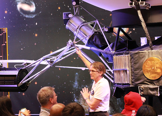
"Voyager Project Manager Suzy Dodd shows off her
spacecraft".
(Source: Bill_D@Flickr)
(click image to enlarge)
2. How It Started
Wired
In 2013, Wired published an article based on an interview with
Suzanne
Dodd, Voyager project manager at the time and, currently, also Director
of the Jet Propulsion's Interplanetary Network Directorate. In the article,
the author, Adam Mann, wrote (his words, not a direct quote from Dodd):
The spacecrafts' original control and analysis software was written in
Fortran 5 (later ported to Fortran 77). Some of the software is still
in Fortran, though other pieces have now been ported to the somewhat
more modern C.
—Adam Mann,
"Interstellar
8-Track: How Voyager's Vintage Tech Keeps Running", Wired,
September 2013.
My impression upon first reading this was that the ground-system mission
control and science data analysis software was written in Fortran and parts
were later ported to Fortran 77 and C. (I now think Dodd was referring to
mission control-related analysis instead of science data analysis.) I'd
never heard of "Fortran 5", but the rest was unremarkable and tracked with
my own experience. In the early 1980s, I worked on the image processing
side of the LANDSAT-4/5 ground system, programming in Fortran 77 on VAX/VMS
minicomputers. The mission-control developers on the other half of our
cubicle farm at NASA's Goddard Spaceflight Center programmed in Fortran
on DEC-2060 mainframe computers. And, in the late 1980s, I was part of
a small team developing a generic, UNIX workstation-based ground system,
TPOCC, for Goddard — programmed in C, of course!
So, aside from the "Fortran 5" oddity, Mann's article was spot-on and
provided an excellent update for me on the Voyager project. Others,
however, inferred more from the quote and, shortened to one sentence
with the "control and analysis" phrase dropped, a misleading form of
the quote spread in the popular press and in numerous hardware and
software forums. The inference or "meme", easily identified by the
"Fortran 5", is that the Voyagers' onboard computers were
programmed in Fortran, etc., etc., as shown here:
The initial software program was Fortran 5, then they were reprogrammed
during flight to Fortran 77, and finally C.
—South Australian Doctor Who
Fan Club Inc. (SFSA), "Voyagers disco party!",
The Wall of Lies, No. 169, Nov-Dec 2017, p. 2.
(4-page newsletter,
PDF)
(I'm not dumping on the fan club. For my example, the juxtaposition of
Doctor Who and disco practically screamed, "Choose me! Choose me!")
Popular Mechanics
I originally dismissed the following 2015 article in Popular
Mechanics as just another knock-off of the Wired article.
However, I was wrong and, upon rereading it more closely, I have to say
it is a superb article. Based on the author's own phone interview with
Suzanne Dodd, the article is about the Voyager project seeking a new
software developer to replace the soon-to-retire
Larry Zottarelli, "the last original Voyager
[software] engineer". From other information I gleaned from the web, it
appears he was one of the original flight software engineers, joining the
project pre-launch in the early-to-mid 1970s. Don't judge the article by
this isolated quote (again, the author's words, not Dodd's):
Know Cobol? Can you breeze through Fortran? Remember your Algol? Those
fancy new languages from the late 1950s? Then you might be the person for
the job.
—John Wenz,
"Why
NASA Needs a Programmer Fluent in 60-Year-Old Languages",
Popular Mechanics, October 29, 2015.
Between Wired and Popular Mechanics, I'm starting
to wish Suzanne Dodd had been a bit clearer in these interviews about what
the programming languages were used for. On the other hand, in her defense,
Dodd has spent decades having to and trying to convey scientific and technical
information in a meaningful way to the public and non-tech-oriented journalists
(in general; I don't mean Wenz).
In this particular case, I expect that knowledge of Fortran is
needed for some of the support software, but not for actually programming
the onboard computers. (Keep in mind that Fortran is not hieroglyphs!
Moderately experienced programmers should be able to pick it up fairly
easily.)
Aside: Algol? Really?! I have long taken some small measure of pride
in the fact that I am one of the few people in the U.S. who have actually
programmed in Algol! When I first caught the computer bug in 1977, I read
one of Daniel
McCracken's Fortran books and his Algol book ... before I even took my
first computer class and got access to a computer. In two classes where
the other students used Fortran, I used Algol because I wanted to try it
out — I liked it. This was the
Norwegian
University (NU) Algol 60 compiler on a Univac 1100-something mainframe.
Unrelated aside: In the Popular Mechanics article, Wenz
contrasts the Voyagers' programmability with that of other spacecraft
with fixed-hardware operation sequencers, such as ISEE-3. The generic,
UNIX workstation-based, misson control system I worked on at Goddard,
TPOCC (mentioned above), was used to replace ISEE-3's Xerox Sigma-based
(if I remember correctly) control system in the early 1990s! Launched
in 1978, ISEE-3 was repurposed in 1982 as the
International
Cometary Explorer (ICE) and underwent a complex set of maneuvers
leading to a rendevouz with Comet Giacobini-Zinner in 1985. (See this
cool
graphic of the maneuvers.) (The mission control system was called
the ICE/IMP control center, so it was controlling two spacecraft, the
second probably being the
Interplanetary
Monitoring Platform, IMP-8.)
3. What is Fortran 5?
A distinct detail in every replication of this meme is "Fortran 5". I haven't
used Fortran since the 1980s, but the unknown-to-me Fortran 5 was an immediate
red flag. In all the online discussions of this subject that I've seen,
no one questions "Fortran 5". Even in a
Fortran
Discourse thread where the users are very knowledgeable about Fortran.
It can't just be me ... please!
On Wikipedia's Fortran page, Fortran 5 is called an
obsolete
variant (i.e., non-standard version) of Fortran:
Fortran 5 was marketed by
Data General
Corporation from the early 1970s to the early 1980s, for the
Nova,
Eclipse,
and
MV
line of computers. It had an optimizing compiler that was quite good for
minicomputers of its time. The language most closely resembles FORTRAN 66.
Data General's Nova
840
minicomputer was introduced in 1973; a contemporaneous DG brochure,
"840:
The Loaded Nova", touts the Fortran 5 compiler in its feature list:
Fortran 5, an extremely thorough, multipass compiler that produces
globally optimized code that's nearly as efficient as assembly
language code
And Data General advertised Fortran 5 with
"It's
a Real Pig": "Pigs are the Smartest Animals in the Barnyard"! The
Fortran 5 compiler was slow because it was taking the time to produce
smaller and faster executables.
(Flickr
image)
Data General's 1978
Fortran
5 Reference Manual
(PDF)
lists 1972 as the first copyright date, incidentally the year the Voyager
project officially began.
4. Fortran V?
I've seen no mention of Data General computers in connection with the Voyager
project in my research, so the use of Fortran 5 on the project seems highly
unlikely.
My guess is that, when speaking to Wired's Adam Mann, Suzanne
Dodd said "Fortran Five", meaning "Fortran Roman Numeral Five",
or Fortran V. This is consistent with Fortran II being known as "Fortran Two"
and Fortran IV as "Fortran Four".
(Fortran III,
in case you're interested, was an unreleased, internal IBM compiler dating
to 1958.)
Fortran V, like Fortran 5, is one of Wikipedia's non-standard,
obsolete
variants of Fortran:
[In addition to Control Data Corporation,] Univac also offered
a compiler for the 1100 series known as FORTRAN V. A spinoff of Univac
Fortran V was Athena FORTRAN.
Now things fall into place. Remember that Suzanne Dodd spoke of "control
and analysis" software. She joined the Voyager team in 1984 as a sequence
engineer in the lead-up to Voyager 2's January 1986 fly-by
of Uranus. These engineers designed/developed sequences of spacecraft
commands for upload to the Voyagers ... work done on one or more Univac
1100-series mainframe computers. From an interview:
DODD: When I first started, I started on a— I don't even remember
the name of it, but I do recall it had an eight-inch floppy drive.
That was our command medium, an 8-inch floppy drive. Not a memory
stick, not even a CD. When we did these designs and plots that
showed—there was a program that you could design an observation,
like you want to make a mosaic over Uranus, and you could lay out the
observation, and then it would tell you what the commands you need
to do it are. That was done on a UNIVAC computer,
so kind of more of a mainframe refrigerator-size computer.
David Zierler,
"Suzy
Dodd (BS '84), Engineer and Deep Space Pioneer", 2023
Caltech Heritage Project, June 9, 2023.
I found more specific information about JPL's mission control computing
facilities in a pre-launch press kit
(Voyager
Press Kit, August 4, 1977, pp. 106-107, PDF):
Mission Control and Computing Facility (MCCF) - three IBM 360-75
mainframes used for the day-to-day operations of the spacecraft,
including command uploads and tracking.
General Purpose Computing Facility (GPCF) - three Univac 1108
mainframes used for "navigation and mission sequence systems ... [and]
prediction programs and detailed spacecraft engineering performance
analysis". These are the systems that Suzanne Dodd would have used.
(Assuming JPL hadn't upgraded the 1108s to newer models in the
intervening 7 years.)
Mission Test and Computing Facility (MTCF) - "three strings of
UNIVAC and Modcomp computers to receive, record, process and display"
the engineering and science data downloaded from the spacecraft.
(The Univac computers here were minicomputers such as the
UNIVAC 1230. The
Modcomp minicomputers
included the MODCOMP II and MODCOMP IV; for some reason,
Tomayko [Chapter 8, Section 3, p. 265] calls them
the ModComp 2 and 4, respectively, though everyone else on the web uses
the Roman numerals!)
Sun Kang Matsumoto is a CCS flight software engineer who joined the Voyager
program in 1985, also, like Dodd, in the ramp-up for the Uranus fly-by. In
a 2016 paper about the Voyager Interstellar Mission (VIM), she gives some more
details about the evolution of Dodd's "control and analysis" software from
Univac to Unix (and thus from Fortran to C, presumably):
During the prime mission and early VIM, Voyager had been using the
JPL-developed software programs called SEQTRAN (to generate sequences)
and COMSIM (to simulate sequences and CCS FSW changes). They ran on
now-antiquated UNIVAC mainframe computers. Shortly after the start
of VIM [in 1990], these programs were converted over to more
modern UNIX-based SEQTRAN and High Speed Simulator (HSSIM). They
were rewritten to maintain the same functionality of the old SEQTRAN
and COMSIM, and tailored for VIM. Rewriting and testing required
significant effort from the developers and the project personnel;
however, the end result is much improved speed and efficiency.
Sun Kang Matsumoto,
"Voyager
Interstellar Mission: Challenges of Flying a Very Old Spacecraft on
a Very Long Mission" (PDF), 2016
p. 4, 2016 SpaceOps Conference, Daejeon, Korea.
SEQTRAN and COMSIM are programs Dodd would have used as a sequence engineer
in the 1980s. I'm a connoisseur of good program names, so I can't fail to
mention Matsumoto's mention of two new programs: VAMPIRE (Voyager Alarm
Monitor Processor Including Remote Examination) and MARVEL (Monitor/Analyzer
of Real-time Voyager Engineering Link)! Matsumoto's paper is well-worth
reading not only for the technical information, but because she provides
a valuable portrayal of how the Voyager team has managed to overcome, by
hook and by software crook, the very real problems of aging hardware at a
great distance. And have done so despite steep technological and budgetary
challenges.
I think (or hope) it is clear by now that, in the 2013 Wired
article, Suzanne Dodd was referring to the ground system software and not
the software running on the flight computers in space.
Okay, Univac and Fortran. But what about Fortran V? I could only find
one instance of "Fortran V" being explicitly mentioned in connection with
a Voyager mission operations program. (I do not include academic papers
whose authors used Fortran V programs to analyze the Voyagers' science data
at institutions outside of JPL; e.g., universities.)
The scarcity of "Fortran V" and "Voyager" on the web is not
surprising. Most programming languages maintain backwards compatibility
between versions, so, for example, a Fortran IV program usually can be
recompiled with a Fortran V compiler without error and with identical
functionality. Consequently, programmers do not in general specify versions
when speaking about languages. A C programmer doesn't say, "I wrote this
program in C89 and later ported it to C99." Instead, it's just an unadorned
"C program". (This is not a slight on the Dodd-Mann remark.)
Also, Univac's Fortran V compiler was available as early as
1966,
so it probably would have been the default Fortran compiler on Univac mainframes
throughout the 1970s. Many Fortran users may therefore have been unaware that
the specific version they were using was Fortran V. (The documentation that I
could find online showed that a generic @FOR invoked the Fortran V
compiler and @FTN invoked the ASCII Fortran compiler discussed in
the second aside below.)
Aside: I anticipate eventually having to eat my pontificating words on
programming language versions! In the meantime ... I couldn't find an
online copy of Univac's Fortran V manual, but the 1970
UNIVAC 1108 System
Description (Section 10, p. 7) had this to say: "FORTRAN V,
being an outgrowth of the earlier FORTRAN languages (in particular,
UNIVAC 1107 FORTRAN IV and IBM FORTRAN IV as announced in IBM form
C-28-6274-1), accepts these languages as compatible although the
reverse is not necessarily true."
Aside: The transition to Fortran 77 on a Univac mainframe would have
been non-trivial. Univac's Fortran 77 compiler, ASCII FORTRAN, largely
accepted Fortran V source code with a few, documented, mostly
Univac-specific exceptions. The big problem, I think, would have been
character sets. Univac's 36-bit mainframes used 6-bit
FIELDATA
characters stored 6 per 36-bit word. The ASCII FORTRAN compiler used
the incompatible 7-bit ASCII character set. (On the Univac 1108
computer I worked on c. 1980, ASCII characters were stored as 9-bit
quantities, 4 per word.) Vanilla character strings in the source code
would just be converted to ASCII without complaint by the compiler,
but programs that depended on specific characteristics of FIELDATA
characters would require changes. That includes programs that must
read or write FIELDATA-compatible tapes. (I have no experience with
ASCII FORTRAN, so these are just my thoughts from perusing the
ASCII
FORTRAN Reference Manual; Appendix A addresses the differences
between FORTRAN V and ASCII FORTRAN.)
Unrelated aside: Circa 1980, I overheard a graduate student remark that
the shell pipe, |, was Unix's gift to mankind and
@ADD was Univac's gift to mankind. He was right!
The Voyager ground-system software I found that was explicitly stated to
have been written in Fortran V is the Orbit Determinaton Program (ODP),
which was also used on other missions. The mathematics in the following
1983 paper is way beyond me, but it establishes the ODP's host system:
To give an idea of the computational burden that is involved, consider a
typical radiometric SRIF/SRIS solution with 67 state variables (Table I).
This model contains only 4 process noise states (line-of-sight acceleration
and 3 camera pointing errors); there are 3500 data points and 132 time
propagation steps. The problem run on a UNIVAC 1110, in double precision,
used 275 CPU s[econds] for filtering; smoothed solutions and covariance
computation used 265 CPU s[econds]. The entire run scenario including
trajectory variational equation integration, observable partials
generation, solution mapping, and generation of smoothed residuals used
4320 CPU s[econds].
...
We note in closing this factorization algorithm discussion that the SRIF
and U-D algorithms that were used in this application have been
refined and generalized, and are commercially available in the form of
portable Fortran subroutines.
—James K. Campbell, Stephen P. Synnott, and Gerald J. Bierman;
"Voyager
Orbit Determination at Jupiter" (PDF), IEEE Transactions on
Automatic Control, Vol. AC-28, No. 3, March 1983, pp. 259-261.
For those not mathematically inclined, the paper is still worth skimming
just for the enumeration of some of the esoteric details of the Voyager
spacecraft that they had to account for in the calculations. We learn
what language was used in a 2008 presentation by Lincoln J. Wood of JPL:
The mainframe computers used include the IBM 7090, IBM 7094,
UNIVAC 1108, and UNIVAC 1100/81. During the 1980s the ODP was
transported to minicomputers, with the software maintained in
both mainframe and minicomputer operating environments to
fulfill the desires of various flight projects. The ODP
consisted of 300,000 lines of code as of 1979, with FORTRAN V
being the primary language.
—Lincoln J. Wood,
The
Evolution of Deep Space Navigation: 1962-1989" (PDF), p. 6,
31st Annual AAS Guidance and Control Conference,
2008, Breckenridge, Colorado.
Shortly after writing the above, I came across this entry in NASA's long-gone,
COSMIC software catalog:
Calculating Trajectories and Orbits
Two programs calculate the motions of spacecraft and landers.
The Double Precision Trajectory Analysis Program, DPTRAJ, and the
Orbit Determination Program, ODP, have been developed and improved
over the years to provide the NASA Jet Propulsion Laboratory with
a highly reliable and accurate navigation capability for their deep
space missions like the Voyager. DPTRAJ and ODP are each collections
of programs that work together to provide the desired computational
results. DPTRAJ, ODP, and their supporting utility programs are
capable of handling the massive amounts of data and performing the
various numerical calculations required for solving the navigation
problems associated with planetary fly-by and lander missions.
They were used extensively in support of NASA's Voyager project.
...
DPTRAJ-ODP is available in two machine versions. The UNIVAC version
(NPO-15586) is written in FORTRAN V, SFTRAN, and ASSEMBLER. (A processor
is supplied for SFTRAN, a structured FORTRAN.) DPTRAJ and ODP have been
implemented on a UNIVAC 1100-series computer. The VAX/VMS version
(NPO-17201) is written in FORTRAN V, SFTRAN, PL/1 and ASSEMBLER. It was
developed to run on all models of DEC VAX computers under VMS and has a
central-memory requirement of 3.4 Mb. The UNIVAC version was last updated
in 1980. The VAX/VMS version was developed in 1987.
—NASA Tech Briefs, September 1989,
p. 33.
A whopping 3.4 MiB of memory required for a lousy 300,000-line program?
Software hogs like that were the reason why we couldn't have nice things
back then ...
5. So What Language was Used?
Assembly Language(s)!
Let's ask an actual Voyager flight software engineer what language was and
is used to program the onboard computers. Perhaps the Voyager Fault
Protection and CCS Flight Software Systems Engineer who's worked on
Voyager since 1985:
Both the AACS and FDS use assembly language. The CCS uses assembly
language and Voyager-unique pseudo code (interpreter). As a result,
it is difficult to attract younger programmers to join the project.
Sun Kang Matsumoto,
"Voyager
Interstellar Mission: Challenges of Flying a Very Old Spacecraft on
a Very Long Mission" (PDF), 2016
p. 6, 2016 SpaceOps Conference, Daejeon, Korea.
In the acknowledgements at the end of the paper, Matsumoto thanks fellow
flight software engineer Larry Zottarelli,
now retired, and Suzanne Dodd, among others, for reviewing the paper.
I assume Zottarelli, Dodd, or one of the others would have spoken up
if they took issue with the above paragraph.
Along with Tomayko's report, Matsumoto's paper was the key source
for this page and answered many of my questions. Many thanks to
Vincent Magnin for sharing this link with
myself and others!
That would be two or three assembly languages: one for the CCS CPU,
possibly a variant for AACS's modified CCS CPU, and definitely another
for the completely different FDS CPU.
CCS Pseudocode
The phrase "pseudo code (interpreter)" made me think of an embedded
scripting language, but that seemed unlikely given the limited amount of
memory in the CCS computer. I puzzled over this for a long time until I
came across a 1997 paper by Rudd et al. Activities onboard the
spacecraft are controlled by sequences. I describe them in more
detail in my Sequences and Simulators
section, but, greatly simplified, a sequence is a list of spacecraft
commands uplinked from Earth that the CCS computer reads and executes.
When the spacecraft were flying by planets (Voyager's prime mission),
sequences could be lengthy and complex. After the planetary encounters,
the two spacecraft veered away from the ecliptic and began what is called
the Voyager Interstellar Mission (VIM), the subject of Matsumoto's
paper. At the beginning of VIM, c. 1990, a higher-level "sequencing
language" was apparently designed and implemented via a pseudocode
interpreter on the CCS computer (and presumably sequence-generation
software on the ground):
The fourth element [of the VIM sequencing strategy] is the use
of pre-defined and validated blocks of commands (high level sequencing
language), rather than the optimized sequence of individual commands
(low level sequencing language) used during the prime mission, to
accomplish desired spacecraft functions. While the use of pre-defined
blocks of commands greatly reduces the effort required to generate and
validate a sequence of commands, there is sometimes an inefficiency
in the number of memory words needed to accomplish a given function.
Fortunately, the VIM science data acquisition requirements and
available on-board sequence storage memory supports the use of
pre-defined blocks of commands.
Baseline Sequence
The baseline sequence is the set of instructions stored in the CCS
memory and is composed of the repetitive spacecraft activities that
execute continuously to return the basic fields, particles, and waves
science data. Eleven predefined spacecraft block routines (equivalent
to software subroutines) also stored in the CCS memory are used by the
baseline sequence to accomplish the desired spacecraft activities.
R.P. Rudd, J.C. Hall, and G.L. Spradlin,
"The Voyager
Interstellar Mission" (abstract), 1997
p. 391,
Acta Astronautica, Volume 40, Nos. 2-8, January-April 1997.
(doi:10.1016/S0094-5765(97)00146-X)
(I don't know if the predefined blocks in the Baseline Sequence paragraph
are among the predefined blocks in the first paragraph.) No more details
or a rationale for pseudocode were provided in the papers. Both Matsumoto
and Rudd et al stress the simpler, repetitive nature of spacecraft
operations in VIM, as opposed to the complex, unique sequences of operations
when flying by a planet. For the latter, there was a rich set of complex
tools for developing sequences on the Univac mainframes
(Brooks, 1988), some of which were ported to Unix
in the move off the mainframes. I wonder if JPL, foreseeing difficulty
in maintaining Voyager-specific sequencing expertise with limited staff
over the coming decades, sought a simpler means of scripting operations
on the spacecraft (substantially reducing or even eliminating the need
for creating new sequences). Rudd et al do hint at this awareness
on JPL's part elsewhere in their paper:
The transition from the Voyager prime mission to the Voyager Interstellar
Mission included significant changes in all areas of mission operations.
Initially these changes included:
- greatly reduced flight team staffing consistent with an extended mission
of reduced complexity;
...
- extensive re-engineering of the Mission Sequence Software (MSS) to
simplify the sequence generation process, and conversion (where feasible)
from a main frame computer to a networked personal computer (PC) based
environment;
...
- implementation of a new spacecraft and instrument sequencing technique
consistent with the repetitive nature of the planned science data
acquisition strategy.
R.P. Rudd, J.C. Hall, and G.L. Spradlin,
"The Voyager
Interstellar Mission" (abstract), 1997
p. 388,
Acta Astronautica, Volume 40, Nos. 2-8, January-April 1997.
(doi:10.1016/S0094-5765(97)00146-X)
When I said a pseudocode interpreter was unlikely in the CCS computer's
4K 18-bit words of memory, I was keeping in mind how the computer had
been chronically short of memory for storing sequences. I am well
aware of interpreters being implemented in constrained memory systems,
having been enthralled in my early computer days by Larry Kheriaty's
256-byte PILOT interpreters (6800 and 8080) in the September 1978
issue of BYTE magazine,
"WADUZITDO: How To Write a Language in 256 Words or Less",
and having read about Tiny BASICs
(Wikipedia)
in Dr. Dobb's.
AACS Power Codes
Before discovering Rudd et al's paper, one pseudocode possibility
I considered was power codes, which the CCS receives from the AACS
and must "interpret" or act upon:
A "power code" is a 6 bit message sent to the CCS computer, which may be
only informational or may cause a power command to switch power to an AACS
component. Such power switching commands are usually the means by which
redundant elements are exchanged. These power codes are an important part
of the fault protection logic, allowing the CCS computer to issue commands
in response to a fault condition. These commands may be a simple power
command (A gyro on) or a command sequence which will turn the spacecraft in
a pattern designed to re-oriented the spacecraft towards the sun from an
entirely random attitude. Some serious faults result in an OMEN power
code, which causes CCS to save the next three power codes (normally lost)
for later analysis.
Assessment of Autonomous Options for the DSCS III Satellite
System, 1981
Prepared for the U.S. Air Force by JPL personnel (Donna L. S. Pivirotto
and Michael Marcucci?),
"Volume III:
Options for Increasing the Autonomy of the DSCS III Satellite" (PDF),
p. 179, Aug. 6, 1981.
Calling power codes "interpreted pseudocode" was a stretch and I couldn't
even convince myself that this was the case. Leaving that aside, Matsumoto
discusses a problem with phantom commands in the "power decoder relay matrix":
The power decoder relay matrix problem that first manifested in 1998 makes
commanding of the spacecraft extremely difficult. Basically, the faulty
decoder may cause an issuance of extraneous power commands in addition to
the intended command.
Sun Kang Matsumoto,
"Voyager
Interstellar Mission: Challenges of Flying a Very Old Spacecraft on
a Very Long Mission" (PDF), 2016
p. 8, 2016 SpaceOps Conference, Daejeon, Korea.
I wonder if this is the interface used to convey the power codes from the AACS
to the CCS. Later, she describes a patch for this error made to
AACSIN, the CCS routine that she notes receives and processes
power codes, but the specific description of the patch again uses the term,
"power commands".
6. Why Assembly?
Since so many commenters in discussion forums had no problem with "Fortran 5",
it might be valuable to examine some possible reasons why the flight software
was written in assembly language.
The CPUs
CCS
There is not much information available specifically about the Voyager
CCS computer, borrowed from the Viking Orbiter. Fortunately,
Tomayko does provide details about the Viking CCS:
In general, the design of the processor was exceedingly simple, yet fairly
powerful, as indicated by the use of direct addressing, a minimal set of
registers, and a reasonably rich set of 64 instructions. The key is that
the design placed relatively light demands on spacecraft resources while
replacing both the programmable sequencer and the command decoder used
in the Mariners. The fact that the processor was later adopted by the
Voyager project as its Command Computer and modified for use as the
attitude control computer is not only a statement of JPL's frugality
but also a testament to the versatility of the design.
(p. 157)
[On the Viking Orbiter, the] Command Computer's central processor contained
the registers, data path control and instruction interpreter. The machine
was serial in operation, thus reducing complexity, weight, and power
requirements. It had 18-bit words and used the least significant 6 bits
for operation codes and the most significant 12 for addresses, as numbered
from right to left. This permitted 64 instructions and 4K of direct
addressing, both of which were fully utilized. Data were stored in signed
two's complement form, yielding an integer range from -131,072 to +131,071.
Average instruction cycle time came to 88 microseconds. Thirteen registers
were in the Command Computer, mostly obvious types such as an 18-bit
accumulator, 12-bit program counter, 12-bit link register that pointed to
the next address to be read, and a 4-bit condition code register that
stored the overflow, minus, odd parity, and nonzero flags.
(Box 5-3, p. 159)
James E. Tomayko,
Computers in Spaceflight: The NASA Experience, 1988
Chapter
Five, Section 6.
Note the 12-bit addresses, giving an addressing range of 0..4095. And note,
in the following, that the Viking CCS flight software engineers masked most
interrupts in routines, thus simplifying code (which reduced memory usage)
and increasing performance:
Viking Orbiter software had to be written in an assembler, which
fortunately had relocatable addresses, simplifying the maintenance task.
The 64 instructions were mostly common to other computers, but there was no
multiply or divide. There were two sets of loads, stores, increments, and
subroutine calls: one used during independent operation and one aimed at
dual operation, so that the two memories could be kept equivalent. Even
though many interrupts were available, most routines as coded had all but
the internal error and counting interrupts disabled. Many routines were
free to run out without being interrupted, in contrast to the highly
interrupted Apollo and shuttle software. Programmers avoided the memory
and processing time overhead required to preserve the current accumulator
and register contents during an interrupt.
James E. Tomayko,
Computers in Spaceflight: The NASA Experience, 1988
Chapter
Five, Section 6, Box 5-4, p. 162.
AACS
The Voyager AACS computer uses a modified CCS CPU (e.g., with the added
index register), so most of the CCS details above apply as well to the AACS:
JPL's Guidance and Control Section wanted to use a version of HYPACE as
the computer for the Voyager. However, there was considerable pressure to
build on the past and use existing equipment. [Edward] Greenberg proposed
using the same Viking computer in all systems on the Voyager spacecraft
that needed one. A study showed that the attitude control system could
use the CCS computer, but the Flight Data System could not due to high
I/O requirements ...
Guidance and Control grudgingly accepted the CCS computer on the condition
it be speeded up. Requirements for active control during the kick stage
burn meant that real-time control programs would have to be written to
operate within a 20-millisecond cycle, roughly three times faster than
the command computer ... Guidance and Control asked for a 1-megahertz
clock speed but wound up getting about three quarters of that. The
attitude control engineers also added the index registers that proved
so useful during the HYPACE experiment. Documentation for the system
still refers to the attitude control computer as HYPACE, even though
its heart was the command computer.
James E. Tomayko,
Computers in Spaceflight: The NASA Experience, 1988
Chapter
Six, Section 2, pp. 177-178.
(In Box 6-1 on the next page in the report, Tomayko uses "HYPACE" to refer
to the AACS despite just pointing out that the term is a misnomer.)
FDS
The FDS CPU was developed especially to meet the high-rate data handling
requirements of the Voyager spacecraft. Designed by Jack L. Wooddell,
the CPU, in the form of a breadboard prototype, evolved in a collaboration
between Wooddell and flight software engineer Richard J. Rice. For some
reason, I picture Wooddell seated in front of a really large breadboard
with a soldering iron in one hand and a wirewrap tool in the other. Rice
is standing beside him with an open laptop in the crook of his left arm,
his right hand is typing on the keyboard, and the changing flight software
is downloaded via wi-fi to the breadboard computer for testing. Wrong era,
I realize, and Rice may well have been left-handed!
Voyager's data computer is different from most small general-purpose
computers in several ways. Its special registers are kept in memory,
permitting a large number (128) of them. Wooddell also wrote more powerful
shift and rotate instructions because of data-handling requirements.
Despite its I/O rate, the arithmetic rate is quite slow, mostly due to
byte-serial operation. This meant 4-bit bytes are operated on in sequence.
Since the word size of the machine is 16 bits, it takes six cycles to do an
add, including housekeeping cycles. If all the arithmetic, logic and
shifting were not done in the general registers, the machine would have
been even slower. Reflecting its role, in addition to the usual ADD, SUB,
AND, OR, and XOR instructions found on most computers, the data computer
has many incrementing, decrementing, and branching instructions among the
36 defined for the flight version of the machine.
Overall, the Flight Data System requires 14 watts of power and weighs 16.3
kilograms. Its computer needs just one third of a watt and 10 volts, less
than the power required for a temperature sensor! At first the estimated
throughput required was 20,000 16-bit words per second. By flight time,
the instruction execution rate was 80,000 per second, with data rates of
115,000 bits per second, much higher than previous Flight Data Systems.
James E. Tomayko,
Computers in Spaceflight: The NASA Experience, 1988
Chapter
Six, Section 2, Box 6-2, p. 184.
Note that Tomayko uses the term byte-serial for non-8-bit "bytes", in
this case, when describing how the FDS CPU's arithmetic logic unit processes
16-bit operands 4 bits at a time. The last two sentences about throughput,
while not wrong, seem to ask the reader to compare apples and oranges.
The breadboard prototype began with the same 4K-by-18-bit plated wire
memory as the CCS computer. I don't know if this means the CPU was
originally designed as a 18-bit processor, but, in any case, it ended
up as a 16-bit processor with 8K-by-16-bit CMOS memory. From Tomayko's
description on p. 183 of Chapter 6, Section 2, my impression is that
the CPU used the same 12-bit addresses as the CCS, but two,
independent-of-each-other address lines were added that effectively
provided a 13-bit (8K) address range for instruction fetches and a 13-bit
(8K) address range for data accesses. The 13th
address bits have to be explicitly set/reset in a separate operation by the
programmer; see the OUT instructions in the code listings under FDS Flight Software. Switching execution
(instruction fetches) from one memory bank to the other is not as
straightforwward as switching data banks, however, as the programmer
probably doesn't want execution to begin at the exact same program counter
offset in the new bank as the old. The FDS CPU solves this problem by
delaying the new 13th address bit going into
effect until the next jump instruction.
If my understanding of Tomayko's description on p. 183 is correct, an FDS
CPU can run code anywhere in its lower and upper 4K words of RAM and,
likewise, can read and write data anywhere in those lower and upper 4K of
RAM. (Accessing a sequence of code or data that crosses the 4K boundary
may or may not be seamless depending on the computer architecture.)
About a month after I wrote the previous paragraph, a commenter in an
online discussion (probably about the Voyager team's workaround for the
November 2023, Voyager 1 FDS memory problem) said that code
is stored read-only in the lower 4K of RAM and the data is stored in
the upper 4K of RAM. I thought either the commenter had a different
interpretation of p. 183 or that JPL simply followed a convention of
maintaining a strict separation of code and data. (Tomayko doesn't
mention read-only.) However, rereading Tomayko another month later
revealed an interesting twist I had overlooked.
Tomayko has three relevant descriptions of FDS memory in Chapter Six,
Section 2:
... JPL's project staff believed that equipment would last longer if
unpowered. Although both CCSs are always powered, rarely are both
Flight Data Systems running, and both attitude control computers are
never turned on at the same time. Full bit-for-bit redundancy is not
maintained in the dual memories. For example, "expended" algorithms,
such as the deployment sequence executed shortly after separation from
the booster, need not be maintained. Both memories are accessed by
the single active processor in each system. The Flight Data System
keeps a copy of its instructions in both memories, but intermediate
data and variables can be stored in either memory.
(p. 174)
... Along with the new chips, the memory changed with an expansion to 8K.
Two "external" address bits were added to flag whether the top or bottom
half of the memory is being accessed. One bit is used to select the
memory half used for data access; the other, for the half used for
instruction access.
(p. 183)
... Also, since the machine can directly address the lower 4K of memory,
programs were to be kept there, with the upper portion for transient
data. Later the flight configuration of the computer evolved to one
processor accessing both memories. Therefore, a copy of the programs
is kept in the lower portion of each memory, but both upper portions
are usable by the single processor as a scratch pad. If dual mode is
required, the memories are separated.
(p. 185)
James E. Tomayko,
Computers in Spaceflight: The NASA Experience, 1988
Chapter
Six, Section 2.
According to the descriptions on p. 174 and p. 185, an FDS CPU runs code
from its own lower 4K of RAM and can read and write data both in its own
upper 4K of RAM and in the other CPU's upper 4K of RAM. So 4K of code
and 8K of data. Note that this is not an increase in physical
memory — each CPU still only has 8K of RAM and the first CPU
is just borrowing 4K from the second CPU. If Tomayko's description on
p. 183 of the two additional address bits is accurate and these bits only
select the lower and upper banks of a CPU's own 8K of RAM, it is not clear
how an FDS CPU addresses the upper 4K of the other CPU's RAM.
Or, more generally, how any of the spacecraft's CPUs —
CCS, AACS, or FDS — access their alternate CPU's RAM,
as the description on p. 174 seems to suggest they are all capable
of doing. On a related note, how are software (and associated data)
updates received from the ground routed to and stored in their
target CPU's memory? For example, if the active CCS computer
is the one that receives and interprets an upload as a software
update for FDS CPU 2, how does the CCS computer directly or
indirectly store the code in FDS CPU 2's RAM?
Dual mode, p. 185, is when both FDS computers are powered up and
running independently of each other. Tomayko states that the two CPUs'
memories are separate in this mode of operation. That may have been JPL's
nominal intention, but the practical needs of the mission would supersede
this convention when necessary. During Voyager 2's flybys of
Uranus and Neptune, the primary FDS CPU (FDS-A) compressed the image data
and the secondary CPU (FDS-B) packaged up the data (and other science and
engineering data) for downlink to the ground. I think it would have been
most efficient for the FDS-B to directly access the compressed data in
FDS-A's RAM, although neither Tomayko nor others describe the exact
mechanism for doing so.
Tomayko's report was published in 1988 in between the 1986 Uranus and
1989 Neptune encounters and he may have written the Voyager section
much earlier. The roles of FDS-A and FDS-B in image data compression
is described in McLaughlin and Wolff,
1985. Cummings, 2025, spoke of an FDS
subroutine, COPY, for copying data from memory A to memory B on
Voyager 1, although there is no indication that COPY
was used on Voyager 2 for transferring the compressed
image data from FDS-A to FDS-B (slide/page 35 in PDF,
51:28
in video).
The FDS is not the fastest CPU on or off the planet:
FDS processing speed (1008 machine cycles per 2.5 ms) (p. 4)
...
While faster image readout rates are both desired and recoverable at the
downlink signal levels available in the extended mission, FDS processing
speed constrains the compressed image readout rate to no faster that 1
image per 4 min, the same as was used at Saturn. At this rate the FAST
compressor in FDS software is compressing 2666 2/3 pixels per second.
(p. 8)
Michael G. Urban,
"Voyager
Image Data Compression and Block Encoding", 1987
International Telemetering Conference, October 26-29, 1987,
San Diego, California.
(Thanks to
LouScheffer
for pointing me to this paper.) The clock rate works out to 403.2 kHz;
if instructions average 5 cycles (e.g., add is 6), that is consistent with
Tomayko's figure of 80,000 instructions per second.
Two sources of information about the FDS computer for Tomayko were the
designer himself, Jack Wooddell, and a paper written by Wooddell, "Design of
a CMOS Processor for Use in the Flight Data Subsystem of a Deep Space Probe":
42. ... Undated at the time, Wooddell thinks he wrote the "Design of
a CMOS Processor for Use in the Flight Data Subsystem of a Deep Space
Probe" in 1974, which makes sense as the development process lasted
from 1972 to 1974.
James E. Tomayko,
Computers in Spaceflight: The NASA Experience, 1988
p. 338,
Source
Notes, Chapter Six.
Steven Pietrobon obtained
a copy of Wooddell's paper from Wichita State University, which houses Tomayko's
Collection
of NASA Documents.
(Dr.
Tomayko was a professor at Wichita at the time he wrote Computers in
Spaceflight and other reports for NASA.)
Note that the paper addresses a "feasibility design" and was written
in 1974, three years before the Voyager launches. Since changes may
have been made in the interval, the paper may not be a totally accurate
description of the final, as-built FDS computer.
The FDS CPU's 16-bit
instruction
set is very spartan, which probably contributes to its low component count
and low power consumption: 326 integrated circuits for the CPU alone, not
including RAM and, I presume, the interfaces to external devices such as
the science instruments and the Digital Tape Recorder. There are 3 hardware
registers (A, B, and C) that are probably built in to the CPU. Tomayko's
128 "special registers" comprise 16 general-purpose registers, 31 memory
pointers, 7 index registers, and 74 counters. These register are "special"
because they're not an integral part of the CPU and instead reside in memory,
the last 128 words of the lower 4K memory bank. Two advantages of this scheme
are (i) a lower component count at the cost of 128 words of RAM and
(ii) frequently used "registers" can be addressed with a 7-bit or shorter
register ID (depending on the group) rather than a 12-bit memory address, thus
producing more concise instructions/code. A big disadvantage is that an
instruction involving a special register requires, aside from the instruction
fetch, a read and/or write to memory, which imposes a performance penalty.
The FDS uses 12-bit addresses to address 4K words of memory. Tomayko's
external address bits — set/reset with OUT
instructions — provide separate 13th
address bits that select the lower and upper 4K of memory for,
respectively, instruction fetches and data reads/writes. A couple of
questions come to mind:
To access the special registers in memory, is the
13th data address bit
temporarily forced to 0? This seems necessary.
When the timer interrupt occurs, are both the instruction and data
13th bits reset to a known state? This
seems necessary so that the interrupt handler at 0x0000 (instruction
address bit: 0) is invoked and with its correct RAM (data address
bit: 1?). (See the description of FDS timer interrupts and P periods
in the Performance Constraints section.)
The FDS is truly a
reduced
instruction set computer, but without the speedy instructions! This is
especially apparent in the computer's primitive subroutine mechanism, which
Pietrobon fortunately explains. The CPU has no call stack and there is a
single jump instruction (but with multiple assembly mnemonics). JMP
saves the program counter (pointing to the next instruction) to hardware
register B and then jumps to the designated 12-bit memory location. This
behavior allows JMP to function as both a regular goto and a
subroutine call. A second mnemonic, JMS, has the same 4-bit
opcode (0) and does the exact same thing, so it is just an alias for
JMP. Pietrobon was not sure why there was a second mnemonic.
My guess is that the programmers use it to distinguish subroutine calls
from gotos in the assembly source code. A simple disassembler would
decode both as JMPs; a more sophisticated disassembler could
possibly examine the instruction(s) at the jump target address and
deduce whether it's a JMP or a JMS.
Okay, a subroutine is called using JMP/JMS. How does
the subroutine eventually return back to the caller? There is no instruction
that returns to the address in register B. Instead, the return is accomplished
with a dynamically generated JMP instruction. The machine code for a
JMP instruction is 0x0TTT, where the upper 4 bits are the opcode (0)
and the lower 12 bits are the target address. When entered, a subroutine
must perform an SRB to save the 12-bit return address in B to a
16-bit memory word; the upper 4 bits are zero, which makes the saved address
a JMP instruction. Executing the saved address/JMP returns
control back to the caller. An implicit call stack is formed by each
subroutine storing its return address in its own local storage, thus
allowing nested, non-recursive subroutine calls.
There are two methods for executing the saved address/JMP that
returns from a subroutine to its caller. Which method to use depends on
the configuration of the memory banks. The two techniques are described
later in the examples of FDS flight software,
Corrupted Memory Block and
Set CMODE from MODE, respectively.
Getting back to Voyager's computers in general, don't be dismayed by the
CCS and AACS CPUs' lack of multiply and divide instructions and the FDS
CPU's slow arithmetic operations. Spacecraft computers don't crunch
numbers. (Out of necessity, in my ground-software experience up to the
mid-2000s. More modern flight computers with more powerful processors and
abundant RAM may have changed this dynamic.) Sensors and detectors return
unit-less raw counts. If these readings are needed in real-time for
autonomous spacecraft operations, it is faster and more memory-efficient
for command sequences or flight software to work with these counts
directly. Otherwise, the ground system can apply its sizeable CPU, RAM,
and disk resources to perform what are called engineering unit
conversions; e.g., the conversion of a hypothetical temperature
sensor's raw 0-255 count to degrees Celsius. The FDS computer is focused
on assembling and formatting science and engineering data for transmission
back to Earth, so fast bit and byte manipulation is more important than
fast arithmetic operations. (Which I learn from Pietrobon are not quite
so fast!)
Memory Constraints
Wise words:
The Voyager flight software design was very heavily impacted by the
limited memory space. Extensive effort and ingenuity was required
to perform the necessary functions in the available space. The
flight software was written in assembly code.
Assessment of Autonomous Options for the DSCS III Satellite
System, 1981
Prepared for the U.S. Air Force by JPL personnel (Donna L. S. Pivirotto
and Michael Marcucci?),
"Volume III:
Options for Increasing the Autonomy of the DSCS III Satellite" (PDF),
p. 179, Aug. 6, 1981.
Words that annoy me:
The computers aboard the Voyager probes each have 69.63 kilobytes of
memory, total.
—Adam Mann,
"Interstellar
8-Track: How Voyager's Vintage Tech Keeps Running", Wired,
September 2013.
An otherwise good article, but ... First, I'm old-school, so the use of
"kilobytes" in the modern 1,000 sense annoys me. Second, the pointless
(and truncated) precision of 69.63 is annoying. Third, the sentence is
wrong because of the confusing wording. The computers don't each
have that much memory. The sum total of memory for all 3 computers and
their 3 backups is 69,632 bytes:
     CCS - 4,096 18-bit words =  73,728 bits =  9,216 bytes
    AACS - 4,096 18-bit words =  73,728 bits =  9,216 bytes
     FDS - 8,192 16-bit words = 131,072 bits = 16,384 bytes
                                               ------
                                               34,816 bytes
                                              x     2 for the backup computers
                                               ------
                   Total for all 6 computers:  69,632 bytes
When examining the memory limitations from a programming standpoint, expressing
the memory size in bytes can be misleading. The CCS computer, for example,
has 9,216 bytes of RAM. Readers may mistakenly infer from that figure
that there are 9,216 addressable code/data units when, in fact, there are
only 4,096 addressable code/data units, a significantly lower number that
more accurately reflects the limits in which the programmers had to work.
For example, if you want a variable that counts from 1 to 10, you can't use a
memory-efficient single byte and must instead use 2¼ bytes (18 bits).
Yes, you can pack multiple data items into an 18-bit word and I'm sure the
Voyager assembly language programmers did just this, but doing so incurs
added memory/performance costs for packing and unpacking the individual data
items. And, yes, clever coding can reduce those costs and or even avoid the
need for packing/unpacking altogether. Which makes a strong case for using
assembly language rather than a higher-level language like Fortran 5!
A given computer's memory holds the flight software code (CPU instructions),
the software's dynamic variables, and uplinked data (tables, command sequences,
and such). Regarding the AACS, Dr. Tomayko wrote (emphasis added by me):
The programmers must have done an outstanding job, considering the slow
processor and limited memory. At launch, only two words of free space
remained in the 4K of plated wire. Tight memory is now a problem
because the scan platform actuators on Voyager 2 are nearly worn out,
and software has to compensate for this during Uranus and Neptune
encounter periods.
James E. Tomayko,
Computers in Spaceflight: The NASA Experience, 1988
Chapter
Six, Section 2, p. 178.
(Interestingly, Tomayko's 1988 report was published after the Uranus encounter
and before the Neptune encounter! He was writing not a history of the distant
past, but an account of a still very much active and prominent project.)
A big chunk of Voyager 2's CCS memory is consumed by the
Backup Mission Load (BML), identified
by name in Matsumoto's paper and described by Tomayko as follows:
As pioneered on Mariner X, a disaster backup sequence was stored in the
Voyager 2 CCS memory for the Uranus encounter, and later for the Neptune
encounter. Required because of the loss of redundancy after the primary
radio receiver developed an internal short, the backup sequence will
execute minimum experiment sequences and transmit data to earth; it
occupies 20% of the 4K memory.
James E. Tomayko,
Computers in Spaceflight: The NASA Experience, 1988
Chapter
Six, Section 2, p. 176.
In other words, if Voyager 2 loses the ability to receive
commands from the ground, the BML ensures that, on its own, the spacecraft
will continue to perform science operations and to downlink science and
engineering data. The original BML (or an early BML) covered a long
period of operations:
Since the failure of one of the receivers on Voyager 2, the spacecraft
has had a "back-up" mission sequence stored in its CCS occupying roughly
one-half of the available sequence memory. Affording protection of limited
mission return in the event of a second receiver failure, and thus
loss of commandability, the back-up mission sequence of Voyager 2 will
control the spacecraft for about 4-1/2 years (until early in 1986) and
includes in it a sequence for a Uranus flyby encounter.
Christopher P. Jones and Thomas H. Risa,
"The Voyager
Spacecraft System Design" (abstract), 1981
pp. 7-8, American Institute of Aeronautics and Astronautics (AIAA),
16th Annual Meeting and Technical Display
on Frontiers of Achievement, May 12-14, 1981, Long Beach, California.
(doi:10.2514/6.1981-911)
Fault protection is very important in a remote unmanned spacecraft and is,
incidentally, one of Sun Kang Matsumoto's areas of expertise. In the 1981
Assessment of Autonomous Options for the DSCS III Satellite
System, Volume III, we learn that 8 CCS
fault routines take up 26.5% of the CCS memory (Table B-3, p. 176) and
9-plus AACS fault routines take up 19.4% of the AACS memory (Table B-4,
p. 180). This suggests that nearly half of Voyager 2's
CCS memory was devoted to the fault routines (26.5%) and the
BML (20%), leaving only a little more than half of the
memory, about 2,200 words, for other CCS functions such as
command sequence storage and processing:
Fault S/W BML Everything Else!
Graph of CCS memory allocation (not a diagram of its layout).
This seems hard to believe and the sizes could well have changed up or down
over the decades since this 1981 study and Tomayko's 1988 report.
A couple of weeks after I wrote the above, I came across a 1987 paper by the
Voyager Flight Operations Manager, published between the Uranus and Neptune
encounters. This paper seems to indicate that, on Voyager 2,
there was even less memory available for sequence storage and processing,
about 1,250 words:
Out of the total CCS memory, the fault recovery routines, other fixed
routines, and flight reserve leave only about 2,500 words available for
sequencing of preplanned activities. These activities involve spacecraft
maneuvers, scan platform movements, data mode changes, data recording or
playback, scientific observations, etc.
...
Since the failure of one of the Voyager 2 command receivers in 1978, that
spacecraft has had a back-up sequence stored in its CCS that occupies
approximately one-half of the available sequencing space. In the event of
a failure of the remaining receiver, this back-up sequence will execute
until late in 1989, allowing for limited mission return including
data-taking during the Neptune encounter.
Terrence P. Adamski,
"Command and Control
of the Voyager Spacecraft" (abstract), 1987
p. 3, American Institute of Aeronautics and Astronautics (AIAA),
25th AIAA Aerospace Sciences Meeting, March 24-26, 1987, Reno, Nevada.
(doi:10.2514/6.1987-501)
(And a couple of more weeks later, I found the exact number: 1,239 words
per CCS computer! See Morris's 1986 paper, p. 173.)
The "fixed routines" would probably have included the core software such
as the executive discussed below, interrupt handlers, communications with
the AACS and FDS computers, ground communications, etc. At the beginning
of the Voyager Interstellar Mission in 1990, a BML was installed on
Voyager 1 too (see Matsumoto's paper, p. 3). It and probably
an updated Voyager 2 BML would have been tailored to the
post-planetary-encounter, interstellar mission. (I suspect that
Voyager 2's original BML, intended for the Uranus and Neptune
encounters, could have been reduced in scope and size afterwards.)
I couldn't find much detailed information about the actual flight software.
Both Tomayko and the Autonomous study describe the
cyclic executive
used on the AACS computer to schedule routines (functions) in regularly-spaced
time slots:
A flow chart of the AACS flight software is shown in Figure 4-14 in
the main body of this report. Normal program execution occurs in
three different rate groups having periods of 10 ms, 60 ms, and 240 ms.
The fourth rate group shown (20 ms) was used only for the Propulsion
Module operation. Functions requiring high rates such as thruster
activation and scan platform stepper motor operations are performed
by the 10 ms logic. The bulk of the attitude control functions, such
as attitude sensor 'reads' and control law algorithms, are accomplished
by the 60 ms logic. The 240 ms logic performs a variety of tasks that
do not require the higher execution rates, such as decoding CCS commands
from the input buffer, fault monitor and correction, and "power code"
processing.
Assessment of Autonomous Options for the DSCS III Satellite
System, 1981
Prepared for the U.S. Air Force by JPL personnel (Donna L. S. Pivirotto
and Michael Marcucci?),
"Volume III:
Options for Increasing the Autonomy of the DSCS III Satellite" (PDF),
p. 179, Aug. 6, 1981.
In a more visual form, here are the 10-ms time slots and the 60- and 240-ms
intervals:
     .-- 10 ms
     v
    |  |  |  |  |  |  |  |  |  |  |  |  |  |  |  |  |  |  |  |  |  |  |  |  |
    |   <- 60 ms ->   |                 |                 |                 |
    |                              <- 240 ms ->                             |
Difficult-to-update, hand-drawn flowcharts are a thankfully retired relic
of the 1970s software industry and I provide here a pseudocode version of
the scheduling algorithm on the AACS. It is not apparent from the
Autonomous study's flowchart, but I do make an assumption
that the 60-ms routines, for example, are not all run in a single 10-ms
time slot every 60 ms. Instead, the per-slot load is lessened by
distributing them over the six 10-ms time slots in the interval. So,
given 60-ms routines ABC and DEF, then
ABC might be run in the 10-ms slots 2, 8, 14, 20, 26, ... and
DEF might be run in slots 5, 11, 17, 23, 29, etc.
    Offset60 = 0
    Offset240 = 0
    EVERY 10 ms DO {
        Run all of the 10-ms routines.
        Run any 60-ms routines scheduled for time slot Offset60.
        Increment Offset60.  If 6 then reset Offset60 to 0.
        Run any 240-ms routines scheduled for time slot Offset240.
        Increment Offset240.  If 24 then reset Offset240 to 0.
    }
Within a time slot, all the scheduled routines must be sure to finish before
the start of the next time slot. The programmers must quantify beforehand
the worst-case execution times for each of the routines and ensure that the
sum does not exceed 10 ms. The programmers probably are counting instruction
cycles for the assembly statements in each routine. (I use the present tense
because this would have been done for the routines prior to the 1977 launch
and still needs to be done for routines updated/uploaded nearly 50 years
later.) If the time exceeds 10 ms and offloading some 60-ms and 240-ms
routines to other time slots is not a possibility, the programmers must
speed up the routines. This is most easily done working directly with the
assembly language. It would be awkward to do this in a higher-level language
because the quanitification still has to be done at the assembly language
level.
Both Tomayko and Autonomous also mention the FDS computer's
P periods, with Tomayko providing a little more detail. With 2.5-ms
time slots, the execution constraints were even more stringent than those
on the AACS. There is no indication of whether or not the FDS had multiple
levels of intervals like the AACS. And apparently the CCS software was also
built on a cyclic executive?
Like the command computer, the data computer has a simple executive. Time
is divided into twenty-four 2.5-millisecond intervals, called "P periods."
Each 24 P periods represent one imaging system scan line. Eight hundred of
those lines is a frame. At the beginning of each P period, the software
automatically returns to memory location 0000, where it executes a routine
that determines what functions to perform during that P period. Care is
taken that the software completes all pending processes in the
2.5-millisecond period, a job made easier by the standardization of
execution times once the direct memory access cycle was added.
James E. Tomayko,
Computers in Spaceflight: The NASA Experience, 1988
Chapter
Six, Section 2, Box 6-3, p. 185.
Unrelated to performance concerns, the use of an executive proves the truth
in Richard Rice's wry quip:
Rice characterized the unique nature of the data computer software
this way: "We didn't worry about top-down or structured; we just
defined functions."
James E. Tomayko,
Computers in Spaceflight: The NASA Experience, 1988
Chapter
Six, Section 2, pp. 183-184.
The executive provided the top-level structure, so the programmers really
were just writing functions to be called when their time slot came up!
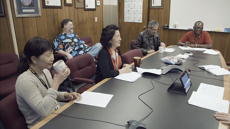
The Voyager team takes a break from worrying
about bit flips and decreasing RTG power! Left to right: Lu Yang,
Todd Barber, Sun Matsumoto, Enrique Medina, and Jefferson Hall.
The picture is from the movie,
It's Quieter in the
Twilight, about 45-50 minutes in, right after the camera
panned away from Chris Jones and Roger Ludwig on the right side of
the table. (Source: JPL's internal newsletter,
Universe,
June 2023,
PDF)
Simulators & Other Random Thoughts
I'm sure you'd just love the reputation of being the guy who lost 2 deep
space probes that had gone the furthest of any manmade object and had been
doing just fine for decades. Through your bright idea for how Things Could
Be Done Better.
—Mike Pellatt,
comment
on The Register forum, October 31, 2015, for
"Think
Fortran, assembly language programming is boring and useless? Tell that
to the NASA Voyager team" (based on John Wenz's Popular
Mechanics article).
In the comments on an Ars Technica article,
Humanity's
Most Distant Space Probe Jeopardized by Computer Glitch"
(February 6, 2024), there was an interesting subthread about the lack of
simulators for the flight computers. (Actually just for the AACS and FDS
computers? Matsumoto mentioned the COMSIM/HSSIM simulator for command
"sequences and CCS FSW changes".) I wanted to address some of the issues
raised in this section, but then I decided to get into some of the more
general issues; hence the "& Other Random Thoughts" in the title.
In every online discussion of anything touching on the Voyager computers,
there are always a number of questions such as "Why didn't they do
this?" and "Why don't they do that?" The answer to the
first question is more than likely, "Well, you had to have been there."
The second question is ably answered by Mike Pellatt above.
Shoestring Space Exploration
The Voyager spacecraft had more than fulfilled their nominal missions after
Voyager 2 flew by Neptune, so they've been living on borrowed
time ever since. However, NASA had long been keeping a close eye on budget
concerns after being raked over the coals by Congress in 1974 for Viking
cost overruns. (See Viking project
hearings in the bibliography.)
Suzanne Dodd spoke of a bathtub effect in personnel levels between
the Saturn and Uranus flybys:
DODD: Now, Voyager went through Jupiter and Saturn, and then it had a
bathtub, because it had five years to get out to Uranus. So a lot of
people left. Because Jupiter and Saturn were like 18— maybe two
years apart, 18 months to two years apart in encounters. Then there
was this lull, so they had to cut— a lot of people left, and/or
they just needed to trim staffing. A bathtub in staffing, because
there was such a long duration.
David Zierler,
"Suzy
Dodd (BS '84), Engineer and Deep Space Pioneer", 2023
Caltech Heritage Project, June 9, 2023.
(McLaughlin and Wolff also refer to the
bathtub effect and describe how JPL tried to reduce the effect between
Uranus and Neptune by spreading the expected work out more evenly in the
interval.)
The "bathtub" after Neptune would be endless and the Voyager team was very
small in the succeeding decades. For those of us interested in the software
side of things, keep in mind that programming would only have been one of
the areas of engineering expertise needed on the team. And the 10-12
full-time employee equivalency means that some, if not many, of the team
were and are working only part-time on Voyager. As knowledgeable people
retired, the remaining members by necessity assumed multiple roles.
The Voyager program was almost cut off completely in the 2000s:
NASA officials said the possibility of cutting Voyager and several other
long-running missions in the Earth-Sun Exploration Division arose in
February, when the Bush administration proposed slashing the division's
2006 budget by nearly one-third — from $75 million to $53
million.
—Guy Gugliotta,
"Historic
Voyager Mission May Lose Its Funding",
The Washington Post, April 4, 2005.
(Voyager's share of the $75 million was $4.2 million.) Thankfully, this
didn't happen, but program leaders like Dodd (who returned to Voyager in
2010) have probably had to fight for funding every year.
In 2024, JPL layed off an eighth of its workforce: 100 contractors in
January, 530 employees in February, and 325 employees in November.
(Los
Angeles Times and
Ars
Technica) This was largely due to the foundering of NASA's
Mars Sample
Return (MSR) mission as its expected cost spiraled out of control and
its expected timeline was pushed farther and farther out. As a result,
NASA has gone back to the drawing board and requested new proposals from
both JPL and private industry. JPL's 2024 MSR budget was cut by $500
million in the 2025 budget and JPL appears to have no other big-ticket
flagship projects in the pipeline that would provide sustained long-term
funding. It is unlikely that NASA will pass unscathed through the incoming
presidential administration and U.S. Congress and, therefore, JPL's smaller,
older projects like Voyager may once again find themselves on the chopping
block.
Between the lack of personnel, the part-time nature of the work, and the
sword-of-Damocles-like budget cut-off hanging over the Voyager project,
the time and money resources available for writing new simulators,
rewriting the flight software in C++ or Python, etc. were scarce. And
both would run up against an insurmountable obstacle: "If it ain't broke,
don't fix it!" We've got a very tenuous connection with two spacecraft,
one 15 billion miles away and the other 12 billion, and you want to do
what?! Paging Mike Pellatt ...
Software Tools
Okay, resources are scarce and have been so for decades ...
In November 2023, Voyager 1 experienced an
FDS memory anomaly. Incredibly,
the JPL ground team diagnosed the long-distance problem and, in April 2024,
began uploading software changes to successfully work around and recover
from the memory problem. In July 2024, the team held an Ask Me Anything
(AMA) session on Reddit. There were some great questions from readers and
some great replies from the JPL team about both the engineering side (e.g.,
the memory anomaly) and the science side of the Voyager project. A couple
of replies left me flabbergasted however:
Unfortunately, we no longer have any test or simulation platforms for
Voyager. Also, we no longer have any of the conventional software
development tools one might expect, such as assemblers/compilers.
Therefore, we had to manually translate all of the code changes into binary
(object code). We created a very exhaustive checklist that we then used in
order to manually examine all of our proposed code changes, to convince
ourselves that the changes were sound. We then iterated over that
checklist multiple times before uplinking the changes to the spacecraft.
-[Dave Cummings]
(Question
and reply)
...
We do not have a flatsat (a hardware-in-the-loop testbed). The spacecraft
have three computers, and we have a working simulator of one of the three.
We are developing simulators of the other two.
When we uplinked the code fix a few months ago, we did not have a simulator
of the computer with the failure, so we had to do our best to analyze the
code fix by reviewing it. One of the reasons we are developing simulators
is so that we can actually simulate such a code fix next time.
-[Kareem Badaruddin]
(Question
and reply)
—Reddit
AskScience
AMA Series: We're the team that fixed NASA's Voyager 1 spacecraft and
keeps both Voyagers flying. Ask us anything!, July 16, 2024.
Cummings and Badaruddin are simply describing the computing environment
in which the memory anomaly effort took place. You have to work with
what is available; you don't get to put off recovering from the anomaly
until new tools are developed. The lack of simulators for the AACS and
FDS computers was not surprising; see my discussion of sequences and
simulators below. (Cummings and
Armen Arslanian played a significant role in the resolution of the
anomaly; see Waggoner.)
I was taken aback by several things. First: There is no FDS
assembler and they manually translated assembly code into machine code?
Was there ever an FDS assembler? If not, over the past 50 years did
no one (a) ever think to write an assembler or (b) think
it worth the effort? If there used to be an FDS assembler, that was
probably early on, the assembler probably ran on a Univac mainframe,
and it probably didn't survive the move off the mainframes
(Linick and Weld, 1992). In this case,
over the past 30 years did no one (a) ever think to port the
old assembler or write a new assembler or (b) think it worth
the effort?
Writing an assembler is not rocket science. Even a simple assembler would
at least avoid the manual translation step. In the late 1970s, I wrote
such an assembler in hand-assembled assembly language for my 6800
microcomputer with 13KB of memory. No labeled memory locations, just
numeric addresses. I would type a program in on my ham-radio brother's
surplus Baudot
teletype and the assembler would generate a machine code/assembly
listing; I'd then manually calculate and annotate the listing with
the relative branch offsets. If no one at JPL could afford the time
to write an assembler, couldn't JPL have reached out to Caltech and
asked a professor to offer an independent study project for credit
to an undergraduate to write an assembler for a computer onboard
one of the most amazing technological achievements of all time?
(I'm not familiar with Caltech other than by reputation, so maybe
this is not something the university would do.)
I understand not being willing to roll out an untested, new software tool
in operations, especially prior to and during the planetary encounters.
However, it's been 35 years since Voyager 2 flew by Neptune.
A new FDS assembler would have had years to prove itself in side-by-side
runs with manual translation. And I understand, as I argued a few
paragraphs above, that inertia is sometimes a good thing and you don't
just willy-nilly rewrite software or procedures that already work. But
one would think someone in management over the past 30 years thought to
themselves, "Hey, these spacecraft are lasting a lot longer than we
expected. Maybe we should consider upgrading the flight software
development and maintenance environment so we are better prepared
to handle the inevitable future problems of aging hardware ..."
Does the flight software team have disassemblers for generating
readable listings from raw memory readouts of the onboard computers' RAM?
These are also not rocket science. In 1985, to enhance listing memory
and single-stepping through code, I added a simple disassembler to an
8086 monitor program borrowed from another project. For Voyager's more
sophisticated purposes, you would want additional inputs of (i)
a memory map indicating instruction/data/failed memory locations and
regions and (ii) a mapping of memory locations to labels.
Second: JPL is currently developing simulators for the FDS and
AACS computers? As I write this in September 2024, both spacecraft
have been in space for 47 years. It is not known exactly how long
both spacecraft will still be operational as far as Earth is concerned.
NASA's Voyager
Frequently
Asked Questions estimates the last science instruments will be turned off
in 2025 and that the spacecraft may continue sending non-science engineering
data until 2036 while enough power remains for the transmitters. The FAQ also
says that Voyager 2 has not yet entered interstellar space, which
it did in 2018, so these estimates are a few years out of date. An
April
2024 news release from NASA reports on how additional power was made
available on Voyager 2 by disabling a voltage regulator,
which will push the shutdown of the science instruments further out.
(The same change was made on Voyager 1 according to
Waggoner.)
Regardless, the Voyager spacecraft are probably in their last few years
or decade of contact with Earth. Why wait until now to build simulators?
This is doubly odd since JPL has had a simulator software framework, HSSIM
(discussed below), for almost 30
years, already used for the CCS computer. I have only found one paper
about HSSIM, Patel, Reinholtz, and
Robison, 1996 (plus two 1997/1998 papers by Saghi, Reinholtz, and
Savory about HSSIM's scheduler). The paper promised delivery of the
CCS simulator to the Voyager project by the end of 1996;
Matsumoto (2016, p. 4) indicates that HSSIM
is in use by Voyager. I have not found any later papers about experience,
good or bad, with HSSIM. HSSIM was implemented in C++ and Tcl; 30 years
later, both of these languages are still in active use around the world,
so expertise in these languages would not have been difficult for JPL to
find, now or in the past.
Good news! Sometime after the July 16 Reddit AMA, JPL completed
the FDS computer simulator, as Badaruddin reported in November 2024.
(Badaruddin was answering random questions from the lecture's internet
audience, so there are understandably some filler words in his responses,
which I have cleaned up in these quotes.)
(09:50)
So most flight teams on flight projects here will test a software patch
in their testbed or in a simulator. We didn't have either of those
things, so we had to analyze the software patch by hand.
(36:27)
We have built a simulator so that if we have to do this again, we've
incorporated everything we knew. So now we actually have simulation
of this computer.
Kareem Badaruddin and Linda Spilker,
"Fixing Voyager:
How NASA Restored Communications with Voyager 1 from Across the Solar
System" (YouTube), 2024
Theodore von
Kármán Lecture Series, November 21, 2024.
This is good news, but is this a limited simulation of the CPU
alone or a fuller simulation of the complete computer and its external
interfaces? The former is sufficient for testing things like the memory
anomaly fixes. The latter would have to simulate interrupts, interactions
with the CCS computer, and direct memory access transfers of data from the
science instruments, to/from the Digital Tape Recorder, and to the
Telemetry Modulation Unit. And so on. The software-based Viking CCS
simulator was this sophisticated (see McEvoy, 1975)
and Voyager's HSSIM CCS simulator may be as well, but even I don't see much
point in or need for building something so complex at this late date.
About a month after the Reddit AMA session, Bruce Waggoner, Mission
Assurance Manager for Voyager and other JPL projects, gave a talk about
the FDS memory anomaly and he spoke of some of the challenges faced by
the team. (The following text is based on the video captions; any
awkwardness in the text is not apparent in Waggoner's speaking, which
flows very naturally.)
(14:07)
So our top priority was to figure out what the FDS was and how it worked.
Because unfortunately the person who was the real expert had retired
decades ago and the person who was their fill-in, their backup, had
retired two years ago.
... These are some examples of some of the documentation we dug up on
the FDS ... So they're all handwritten. The one up on the upper left
[of the presentation slide] has got some handwriting. These are
very dim circuit diagrams and these are handwritten timelines for how
to change FDS processors. So this was ... We were lucky to find these.
Some things we couldn't find. A lot of it was like this. That had been
scanned. And [frequently] — these sources were contradictory,
ambiguous. Why? Because we changed the way the spacecraft worked with
every planetary encounter and entering the VIM and when things broke.
So there was a lot of opportunity for ambiguity to arise in the documents
over the course of 50 years.
This is my favorite example. So this is a page out of an important FDS
document. The change bar on the far side indicates it's a change, but
somebody went in and made the very cryptic circle of the sentence and
crossed it out. I have no idea to this day what it means. I have no idea.
Maybe it was important. Maybe they crossed it out, because they thought
crossing out was important. I'm not sure.
So there were other cases like this. So we were even so confused in some
cases, we weren't sure if we were sending data to the FDS —
should it be least significant bit first or most significant bit first?
We had that level of uncertainty. So the only thing we could do is dig
in and research more and debate. So we had a lot of debates between our
flight team and tiger team, trying to figure out what the best thing is
to do. But ultimately, we had to suck it up and guess at some point.
And we made the right guesses, which is good.
...
(26:44)
We didn't know we had the right instruction set. I showed you the
instruction set there [in an earlier slide]. We didn't know
that was the one used to build the software, back when there was an
assembler. We didn't know the source code version was the same as
what was running on board the spacecraft. We had a listing of the
code, but it was a Microsoft Word document, optical character
recognition scans. We didn't know if there were errors in it.
We have no assembler. So they're just playing with bits.
Bruce Waggoner,
"Saving
Voyager 1! - Bruce Waggoner at !!Con 2024" (YouTube), 2024
!!Con 2024, August 25, 2024, Santa Cruz, California.
"Instruction set" usually refers to the set of instructions a CPU
is capable of executing and that hasn't changed over the years, so
I believe Waggoner might be referring to the assembly language
mnemonics/syntax or to the source code generally.
The lack of up-to-date source code is a big red flag. According to
Matsumoto (2016, p. 7), Voyager 2
has an "annual full [memory readout]" of all 3/6 computers and I assume the
same is done for Voyager 1. JPL should have had a source code
listing current as of the last FDS memory readout. If a disassembler
wasn't available before the anomaly effort, one should have been written
as part of the effort, with the memory block flags and location-label map
I mentioned earlier built iteratively as the engineers explored the code.
I realize the code is a rat's nest of peeked and poked patches over decades,
but, if the CPU can execute it, a disassembler can certainly make sense of
the code. Please tell me the anomaly team weren't hand disassembling the
new memory readout with an old Microsoft Word document up on the screen.
I'm of two minds about the poor documentation. On the one hand, I get
the impression of a skunkworks environment at JPL — highly
innovative but not so good on the follow-up production and management
of documentation, etc. In this context, I can understand, for example,
NASA's decision on the Mars Viking project
to bring in a large aerospace contractor (Martin-Marietta) to build the
Viking Lander. (The skunkworks impression is just an impression; JPL
is obviously a very large organization in its own right.) On the other
hand, it has been 50 years and it is easy to imagine documentation
bit by bit dropping between the cracks or disappearing into obscurity in a
large government warehouse à la the end of Indiana Jones's
Raiders of the Lost Ark.
Stepping down off my soapbox ... From reading about the software
challenges and accomplishments on Voyager and on other JPL projects,
it's obvious that JPL has (and had) many highly talented and motivated
software developers. So I'm honestly puzzled by this glaring lack of
tools. At this late stage, I can understand preferring to work on
shinier objects, but in decades past Voyager was the shining object.
(Okay, not that shiny after the planetary encounters, but I imagine
there was a significant amount of flight software programming during
the transition to the Voyager Interstellar Mission, enough to warrant,
for example, an FDS assembler.)
As an outsider looking in, it is easy for me to haughtily pronounce
judgment on what the Voyager project should have done or should be
doing. I do realize that, at this late date, actual and
potential failures in the computers are not the only problems facing
the Voyager team, problems that can't be remedied simply with software
changes. The following slide from a 2020 presentation gives you some
idea of the range of issues that keep the extremely small Voyager team
up at night. The full presentation has more details about the listed items:
Spacecraft Operations
Finally, a few words about spacecraft operations. The constraints on
flight operations range from the mundane to out-of-this-world. Examples
of the mundane are staffing levels. Adamski (p. 4)
notes that during the long, hopefully uneventful, cruise intervals
between planets, operations were limited to daytime hours since the control
center was not manned around the clock; this was a contraint taken into
consideration in the design of a sequence.
Skipping in-this-world concerns such as earthquakes (see
Kohlhase, p. 120) and going straight to
out-of-this-world constraints, everyone seems to know that the Voyager
spacecraft are very far away and that it takes about 40 hours to send a
command and receive a response back. (This is called the Round Trip
Light Time, or RTLT.) However, I sometimes wonder if people also
understand that the Voyager team is not in constant contact with the two
spacecraft. You can't just make a change to the flight software, recompile
it, and uplink it to the spacecraft.
I use 40 hours as a nice round number for RTLT. More specific values
in 2024 are about 45 hours for Voyager 1 and about 38 hours
for Voyager 2. If you need even more accuracy, the real-time
Voyager
Mission Status page has the hours, minutes, and seconds of the one-way
light times. As I noted in the "Introduction",
the distance of each spacecraft goes up and down depending on whether the
Earth in its orbit is falling behind or catching up with the spacecraft.
As the distance changes, so does the transmission time.
Communications with the Voyager spacecraft are handled by NASA's Deep Space
Network (DSN), which consists of three tracking stations spaced about
120° of longitude apart in
Goldstone (California),
Madrid (Spain),
and Canberra (Australia). Each
station has a 70-meter dish antenna, multiple 34-meter antennas, and others.
According to Matsumoto's predictions (p. 6), by
now (2024), a 70-m antenna is required to send commands to either Voyager
spacecraft and a 70-m antenna or two 34-m antennas are required to receive
engineering and science data.
Aside: A 70-meter dish antenna is 230 feet in diameter, ¾ of
the length of an American football field, as you can see in this fanciful
picture of the Goldstone 70-m antenna placed in Pasadena's Rose Bowl
stadium! (Pasadena is also home to JPL. Source:
The Voyager Neptune Travel Guide,
p. 28.)
The Voyagers are not the only spacecraft using the DSN, so the Voyager team
must request and compete for transmitting and receiving time on the DSN.
(At DSN Now, you
can see in real-time which antennas are talking to which spacecraft.) When
scheduling time, the team must take into account the 40-hour round trip
light time. Depending on a variety of factors, it is possible that they
might have to settle for time slots more than 40 hours apart, in which case
the team must ensure they can still verify the results of an operation.
Matsumoto gives an example:
Command Loss (CMDLOS) timer, the timer that triggers CMDLOS FPA entry when
it reaches to the pre-set value, is set for six weeks. It is still
desirable to send the command to reset the timer every week but it is a
best effort approach based on the DSN resources, usually without downlink
coverage for command receipt verification. (The receipt of a command is
verified indirectly by the CCS hourly status data when the telemetry is
available.)
Sun Kang Matsumoto,
"Voyager
Interstellar Mission: Challenges of Flying a Very Old Spacecraft on
a Very Long Mission" (PDF), 2016
p. 5, 2016 SpaceOps Conference, Daejeon, Korea.
After passing Saturn, Voyager 1 angled north of the ecliptic
(planetary) plane as it headed out into space. After passing Neptune,
Voyager 2 angled south. Consequently, communications
with Voyager 2 are only possible via the Canberra DSN station
in Australia. This became a problem in 2020 when Canberra's 70-m dish was
taken offline for 11 months for upgrades. Voyager 2 continued
transmitting data to the smaller dish antennas, but commands could not be
sent to the spacecraft. Contact was successfully reestablished in early
2021 when the 70-m dish came back online. (The prior preparation and the
actual downtime are featured in the 2022 film,
It's Quieter in the
Twilight, about the Voyager team.)
The DSN stations send commands to the Voyagers at a radio frequence of about
2.1 gigahertz. Because of the Earth's rotation (as well as the revolution
of the Earth around the Sun and other factors), a dish antenna as a whole
moves around in space. As a result, the relative motions of the antenna
and the spacecraft (which is also moving) cause a continuously varying
Doppler shift
in the radio signal's frequency as seen by the spacecraft.
(Kobele, p. 13, says that the Doppler shift can be
up to 3 kilohertz during a DSN pass.) The Voyager's command receivers were
designed with this in mind and use a phase-lock loop (PLL) circuit
to detect, lock onto, and maintain the lock on a varying frequency signal
within a 100-kilohertz range.
In April 1978, less than a year after launch, ground control forgot to reset
Voyager 2's Command Loss timer and the aforementioned CMDLOS
function was tested for real when the timer expired. The CCS computer thought
the primary receiver was no longer working, so it switched to the backup
receiver. Unfortunately, the backup receiver's PLL circuit had failed
partially prior to this switchover and the receiver could not lock onto the
command signal. After 12 hours, the CMDLOS function switched back to the
primary receiver and contact was reestablished. "Phew!", as Wordle likes
to say. A half-hour later, the primary receiver failed completely.
Back again, a week later, to the backup receiver that couldn't
receive. (The CMDLOS timeout value was 1 week for the primary receiver
and 12 hours for the backup receiver.)
(Note that human error triggered these two problems, it didn't
cause them. The partial failure of the backup receiver's PLL circuit had
already happened and the complete failure of the primary receiver was just
waiting to happen. The project was actually fortunate that this occurred
early on and not later, for example, in the middle of flying by Jupiter.)
I don't know how they did it, but somehow the engineers figured out that
the backup's PLL circuit was limited to a single, nominal frequency with
a tolerance of only 100 Hz — that's 100 cycles-per-second in a
2.1 billion cycles-per-second radio frequency. Wow! Since
Voyager 2's receiver could no longer compensate for the Doppler
shift (up to 3 kHz during a pass), the DSN transmitter had to compensate by
sending a varying frequency signal that canceled out the pre-calculated,
expected Doppler shifts, thus delivering a constant-frequency signal to
the spacecraft.
Note: The 100 Hz and 100 kHz (PLL) figures are from
Ludwig and Taylor, pp. 39-40;
other sources have slightly different values, but the same
three orders of magnitude difference.
Would that things were so simple! The frequency at which the backup receiver
is listening for commands is called the best-lock frequency (BLF).
The BLF is extremely sensitive to the temperature of the receiver and small
changes in temperature cause shifts in BLF exceeding the 100-Hz range. Many
activities on the spacecraft cause these temperature changes. To cope with
this added difficulty, the ground system must (1) limit uplinks to
no-activity periods when the receiver's temperature is stable and (2)
regularly recalibrate the BLF. The former is accomplished by following a
period of activity with an uplink-free, 24- to 72-hour command
moratorium that gives the temperature time to stabilize. The latter
is done with a scatter-shot approach, sending something (probably a test
command of some kind) at multiple frequencies and seeing which one actually
gets through. (McLaughlin and Wolff, p. 5,
describe using the scatter-shot approach to uplink emergency or time-sensitive
commands during active periods: send the same command at multiple
frequencies in hopes that one will get through. This technique may have been
used in planetary fly-bys to upload onboard sequence updates.)
Amazingly, all this was made to work and Voyager 2 successfully
flew by Jupiter, Saturn, Uranus, and Neptune and returned valuable images
and science data under these operational constraints. And continues to do so.
(The 2020 MAG-roll-gone-awry in It's
Quieter in the Twilight was probably followed by a command
moratorium.)
The Voyager engineers were (and are!) resourceful:
An alternate solution to Voyager 2's radio problem considered
by NASA was to send commands through one of the science instruments, namely
the planetary radio astronomy receiver. Tests conducted during September
1978 using the Stanford radio telescope indicated less received signal
strength than had been anticipated, and the approach required both major
changes in the onboard computer programs and the construction of a suitable
ground transmitter facility. Implementation would cost an estimated $10
million ($7.5 million facility, $2.5 million project) and would require
about twenty-four months to develop. Realizing that if the capability were
never used, NASA would be open to criticism for having built an unnecessary
facility, the Voyager Program Office decided against the planetary radio
astronomy solution.
—Andrew J. Butrica,
"Voyager:
The Grand Tour of Big Science", Chapter 11,
footnote
79, in
From
Engineering Science to Big Science, Pamela E. Mack, ed., 1998.
Varying the DSN transmission frequency to compensate for Doppler shift was
successfully tested in April 1978 per Butrica, so I'm not sure why use of
the Planetary Radio Astronomy receiver continued to be investigated and was
later tested in September 1978. Perhaps there was a fear that the backup
command receiver might fail completely.
Various sources attribute the crippling of the backup receiver to the
failure of a tracking-loop capacitor in the PLL. Kobele gives a bit
more detail:
It is surmised that the failure mode is a resistive short in the tracking
loop capacitor due to particle migration through the dielectric material.
It has been demonstrated that particles which have not yet completed their
migration can be destroyed when the capacitor charge is maximized by
periodically pulling the uplink signal to the extremes of the loop
bandwidth.
—P. Kobele,
"Maintainability
of Unmanned Planetary Spacecraft: A JPL Perspective" (abstract), p. 14,
American Institute of Aeronautics and Astronautics (AIAA)/NASA
Maintainability of Aerospace Systems Symposium, July 1989, Anaheim, CA.
(doi:10.2514/6.1989-5070)
It's too late to do Voyager 2's capacitor any good, but
"pulling the uplink signal" is performed periodically as preventive
maintenance on Voyager 1:
The short in the backup receiver tracking loop capacitor was a known
generic risk, and the failure raised the concern that the problem could
occur on Voyager 1. As a result, immediate attention was given to devising
a special conditioning test for Voyager 1 which would test the capacitors
in both the prime and backup receivers and stress incipient shorts with
sufficient energy in the capacitor to clear (burn out) any short that
occurred. This conditioning test has been carried out regularly on Voyager
1 since its introduction in 1978.
—Raymond L. Heacock, interview in David W. Swift,
Voyager Tales: Personal Views of the Grand
Tour, p. 156, 1997.
Sequences and Simulators
Regarding simulators, you'll find comments such as, "Give me the CPU details
and I'll whip up a simulator over the weekend." These comments and the earlier
questions are not bad and I admit to often having similar thoughts myself.
However, as software developers, we of all people should have —
but don't have — an instinctual reaction that nothing is
ever as simple as it first seems.
In this case, simulating the CPU may be the least complicated part of a
flight computer simulator, itself part of a larger system. It turns out
that, much to my amazement, the engineers back in the 1970s —
without JavaScript and Rust, without gigabytes of RAM, and without
55-MB web pages —
somehow managed to write sophisticated and complex programs! (The link is
to a page about JavaScript bloat, not to an actual 55-MB web page.)
The following discussion is largely based on the papers by
McEvoy (1975) and Adamski (1987)
about the Viking and Voyager simulators, respectively. The descriptions here
are my understanding of the systems, which may likely be imperfect.
The intended takeaway is that the systems were complex and I think that
will be made clear in spite of any errors.
Linick and Weld's 1992 paper examines the
streamlining of the prior sequencing process, as described in Adamski,
for the Voyager Interstellar Mission (VIM), an effort that successfully
met two goals, among others, of moving off the Univac mainframes and
operating with greatly reduced personnel in the long term. The paper
provides a somewhat managerial evaluation of the changes and doesn't
provide the new hardware and software details I would have liked.
NASA's 1997 30-Year Plan describes the
VIM sequencing strategy — the long-term baseline sequence
and the shorter-term overlay and mini-sequences — and
includes functional details of the baseline sequence and the Backup
Mission Load (activated when a spacecraft is unable to receive commands).
Note something that I completely missed in my initial readings. The
Viking Orbiter had only one computer (and its backup), the CCS.
Its Attitude Control Subsystem (ACS) and its Flight Data Subsystem (FDS)
did not have their own computers. The Viking FDS did have a
1K-by-8-bit plated-wire memory:
The FDS memories were required to perform a number of essential tasks
and were additionally used to accomplish a variety of FDS housekeeping
functions, including reading engineering identifiers for the flexible
formats; buffering MAWDS, VIS, and IRTMS (A/PW) science data; storing
and updating VO time; storing PN sequences for the VIS and science
formats; executing memory-alteration commands from CCS; performing
most of the science format multiplexing; and counting TV pictures
taken and controlling related FDS logic.
—Neil A. Holmberg, Robert P. Faust, and H. Milton Holt,
Viking '75
Spacecraft Design and Test Summary, Volume II: Orbiter Design
(NASA Reference Publication 1027), p. 61, November 1980.
Because of signal transmission delays, the Viking and Voyager spacecraft were
designed to function autonomously, a form of operation that depends heavily on
stored command sequences as opposed to single, separate, "real-time" commands.
Consequently, simulation is especially geared towards the testing of command
sequences.
In the introduction, I defined a command sequence as a sequence of commands,
but they are much more than that. A sequence is composed of blocks,
each of which consists of:
Events - are actions (?) that may or may not be associated with
spacecraft commands. In McEvoy's sample Viking Orbiter block
(Figure 9, p. 414), events with CCS spacecraft commands are actions
targeted to the external subsystems such as the ACS and FDS. In one
entry, the CCS instructs the ACS: "Inertial mode; stop roll turn;
stop yaw turn; negative turn direction". Events without CCS commands
are actions taken internally by the CCS, as in this CCS event: "Disable
the ACS accelerometer calibration within the CCS".
Data - any data required by the block; e.g., tables.
Flight software - is the non-core software needed to support the
commands/events in the block.
In developing a sequence, engineers such as Suzanne Dodd could draw on
previously defined blocks in the block dictionary for subtasks, much
like programmers use functions from libraries. Blocks used in such a manner
are customized via block options and pull in their own required flight
software. A Viking block's flight software was stored as OSTRAN macros
(McEvoy, p. 415); OSTRAN was the Viking counterpart to Voyager's SEQTRAN.
The output of OSTRAN is assembly source code that is passed on to an
assembler and linker, ultimately resulting in the memory load (containing
sequence, data, and flight software) that will be uplinked to the spacecraft.
It appears that the flight software resident in memory consists of (i)
the core software that is always present (executive, sequence processing,
fault protection, etc.) and (ii) only the non-core software needed
to support the currently loaded sequences.
Throughout the development and simulation of sequences, there are automated
and human checks for physical and operational constraint violations. When
a violation is detected, engineers determine how serious the violation is
and, if necessary, go back to the drawing board to remedy the problem.
The engineers also need to verify that a sequence actually does what it
is supposed to do; e.g., take a picture of Neptune. Consequently, the
design-develop-test cycle for sequences is an iterative process.
A block diagram for the Voyager simulator (COMSIM) would look similar to that
of the Viking Orbiter simulator (OCOMSM) below. (I think — I
haven't been able to find detailed information about Voyager's simulator.
Incidentally, the Viking Lander simulator was called LCOMSM.) Note
that the nested CCS and FDS simulators are subsystem simulators.
I'm puzzled by the absence of an ACS simulator. The Viking Data Storage
Subsystem, DSS, handled the Digital Tape Recorder (DTR), a function taken
over by Voyager's FDS.
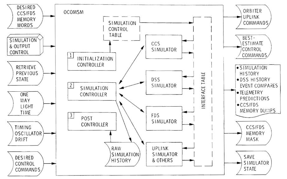
Viking Orbiter Simulator Functional Block Diagram
(click image to enlarge)
(McEvoy, Figure 11, p. 417)
The simulator outputs on the right side of the diagram are very important
and provide:
Visibility into the internal sequence processing to the sequence
and flight software engineers.
A step-by-step timeline for the flight controllers to follow (after
the fact because of the time delay!) as the sequences are actually
executed on the spacecraft.
The step-by-step timeline is called the Sequence of Events (SOE) on
Voyager:
In addition to the blocks of load commands, the sequence generation process
provides other products that are used in the command and control of the
spacecraft. A Sequence of Events (SOE) is produced that is a printed,
time-ordered listing of the activities contained in the CCS sequence.
Performance predictions are generated for power usage, scan platform
pointing, and other spacecraft functions. Additional uplink commands may
also be generated along with the main sequence. These commands are held
for subsequent transmission at pre-identified points in the sequence in
order to perform discrete functions or enable checkpointed events.
Terrence P. Adamski,
"Command and Control
of the Voyager Spacecraft" (abstract), 1987
p. 5, American Institute of Aeronautics and Astronautics (AIAA),
25th AIAA Aerospace Sciences Meeting, March 24-26, 1987, Reno, Nevada.
(doi:10.2514/6.1987-501)
A spacecraft is more than just its flight software and simulators must also
simulate the hardware. McEvoy suggested
APL
for both describing and simulating hardware, although he didn't come right
out and say they used APL. I wasn't aware of APL's role in the hardware
realm, but it's a real thing. (I do question the widely asserted notion
that APL was originally a hardware description language. That doesn't seem
to agree with Kenneth Iverson's contemporaneous writings and later recountings
of APL's history, but it is a Fortran 5-like rabbit hole that I'll leave to
someone else to explore!)
One difficulty in modeling digital hardware is the different languages
used in the hardware and software disciplines. Hardware description
languages that describe hardware at the logic-gate bit-time
register-transfer level provide a commonly understandable detailed
definition that can bridge the gap. The APL language itself provides
an excellent basis for describing digital hardware. Power-on-reset
states and hardware idiosyncracies, that could affect a sequence,
must be considered in the modeling stage. Any of these that could
affect operation of the hardware, software, timing, or other subsystems
should be modeled.
Maurice B. McEvoy,
"Viking
Orbiter Uplink Command Generation and Validation via Simulation"
(PDF), 1975
p. 417, The Institute for Operations Research and the Management Sciences
(INFORMS)
Winter
Simulation Conference 1975 Conference Proceedings.
Voyager's CCS subsystem simulator would also have looked similar
to Viking's:
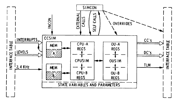
Viking Orbiter CCS Simulator
(click image to enlarge)
(McEvoy, Figure 12, p. 418)
Each of the CCS, AACS, and FDS subsystem simulators would have had to simulate:
- the two CPUs,
- the internal elements of the subsystem (e.g., memory banks),
- interfaces with elements external to the subsystem (including
interfaces with the other computer subsystems),
- cross-strapping (switching) between primary/redundant elements both
internal and external,
- and the timing of everything.
The two CCS CPUs could also work independently of each other and not in a
strict primary/backup relationship. Despite my listing of the simulation
"requirements" above, there is a lot I don't know about the simulators:
Were CPUs simulated in software or were actual hardware spares used?
For CPUs simulated in software, was the simulation at the instruction-set
level or was it a simulation of the CPUs' actual electronic circuits
(e.g., using APL)?
And similar questions about interfaces with the various non-CPU elements:
Was an interface simulated at a logical level or as an electronic circuit?
Or was a real interface with a hardware spare used?
What elements could be cross-strapped? And was cross-strapping simulated?
In other words, my ideas about the simulators are largely guesswork. McEvoy
does provide a few more details about the CCS simulator, although some of my
questions are still unanswered:
The Computer Command Subsystem (CCS) simulator (Fig. 12) accurately
models the Block redundant CCS processors, output units, and memories at
the instruction and register transfer level. The accuracy with which
software programs (in the memories) are simulated is dependent primarily
on the accuracy with which the bit-time clocks can be calibrated during
flight and timing accuracies of the 32 priority interrupts and 24 level
indicators. Output simulation consisting of discrete commands (relay
closures), coded commands, and telemetry data can be routed through
either or both output units. A hardware and software self-test must
be satisfied before access can be obtained to an output unit.
(p. 418)
...
The large amount of time used to simulate uplink command decoding is
due primarily to the CCS hardware and software self-test activity,
which in turn is affected by the FDS engineering telemetry rate and
format. (p. 419)
Maurice B. McEvoy,
"Viking
Orbiter Uplink Command Generation and Validation via Simulation"
(PDF), 1975
The Institute for Operations Research and the Management Sciences (INFORMS)
Winter
Simulation Conference 1975 Conference Proceedings.
(I don't understand the purpose of the "hardware and software self-test"
in the last sentence of the first paragraph. Was this done on the actual
spacecraft? The later sentence seems to indicate "Yes". I can understand
self-tests performed repeatedly in the background or prior to a set of
operations, but I am perhaps overestimating the frequency of the self-tests.)
So, spacecraft simulators are complex systems. What did the Voyager simulator
look like?
The validation end of the software development process was handled by the
Capability Demonstration Laboratory (CDL). Completed after the initial
software was produced, it was a collection of either breadboard or flight
surplus computer and science hardware, and its interfaces interconnected in
the same way as those on the actual spacecraft. Its function is identical
to that of the Shuttle Avionics Integration Laboratory (SAIL), in which
both software and hardware changes could be tested to see if they
functioned successfully.
James E. Tomayko,
Computers in Spaceflight: The NASA Experience, 1988
Chapter
Six, Section 2, p. 175.
And the CDL lapsed into disrepair:
In addition, the [Voyager flight team] also has to work around a lack
of a hardware test bed, the limited memory of on-board computers, and
antiquated programming languages.
The Capability Demonstration Lab (CDL), the testbed used during the prime
mission, could not be maintained and had to be abandoned at the start of
VIM. The failures of the testbed were too often, even in pre-VIM, due to
aging hardware and disappearing repair expertise. The project had to move
to a new location in early VIM and the CDL did not survive the move. There
are no simulators for the AACS or FDS and only the CCS has a simulator,
i.e., HSSIM. As a result, any FSW changes other than something very simple
have to be done in the CCS.
Sun Kang Matsumoto,
"Voyager
Interstellar Mission: Challenges of Flying a Very Old Spacecraft on
a Very Long Mission" (PDF), 2016
p. 6, 2016 SpaceOps Conference, Daejeon, Korea.
The last sentence above suggests to me that a non-trivial change to the AACS
or FDS flight software is considered risky and that, if possible, it is
better to leave the existing AACS/FDS software as-is and have the CCS take
over responsibility for the changed functionality. That's my impression
at least; given the lack of rigorous simulation capabilities, I think it's
a sensible decision.
Oddly, searching on Google for JPL's "Capability Demonstration Lab", mentioned
by both Tomayko and Matsumoto, only brings up a couple of references to
Matsumoto's paper; on Bing, you get a single result ... for JPL's Cyber
Defense Laboratory! By a strange coincidence, a couple of hours after
reading the previous sentence, I was reading McLauglin's & Wolff's paper
about the preparations for Voyager 2's Uranus fly-by and I came
across the most detailed description of the CDL yet. Which is not saying much,
but the passage below does give a good picture of a flight software engineer's
life!
The physical actions and movements in the Digital Tape Recorder (DTR)
produce "equal and opposite reactions" in the spacecraft and thus affect
the spacecraft's attitude. After the Saturn encounter, a routine, DSSCAN,
was added to simultaneously fire attitude control thrusters when performing
high-rate tape operations, thereby greatly reducing the time it takes for
the spacecraft attitude's rate-of-change to slow enough to begin the next
science operation. (A savings of over 3 minutes in the case of the
end-of-track turnaround, valuable time during the all too brief hours of
closest approach.) That's my understanding; it's not clear which computer
DSSCAN was added to, AACS or CCS.
Note how Voyager 1, its mission already completed, was used
as a test bed for the Voyager 2 FSW modifications. Note also
that the AACS and CCS programs were not reassembled, but instead
patched, a practice that had been ongoing since launch. What a nightmare
the onboard software must have become! I don't know how long the practice
continued, but it makes the VIM team's reluctance to modify the AACS software,
per Matsumoto, even more understandable.
The DTR is mounted on the spacecraft such that its angular momentum is
introduced into the yaw and pitch axes of the spacecraft with almost none
going into the roll axis. DSSCAN was first programmed to introduce
cancelling momentum in the yaw axis only. The modification to the AACS and
CCS software took place in an environment of a scarcity of available memory
so that, from a programming point of view, it had to be carefully fit in.
The "patch" was carefully tested in the Voyager Capability Demonstration
Laboratory (CDL) before loading onboard Voyager 1. (The AACS and CCS
programs were modified without being reassembled as is the case with all
AACS and CCS changes since launch.) The CDL is a digital/analog simulation
of many of the spacecraft capabilities. Modifications or tests of any
degree of complexity are done first, whenever possible, on Voyager 1 before
implementation on Voyager 2, a reflection of the fact that Voyager 2 still
has two planetary encounters scheduled while Voyager 1 has none.
Once onboard the spacecraft, DSSCAN was tested during periods of DTR
operation to determine empirically how many thruster pulses should be used
to counteract a DTR event. For example, tests on Voyager 1 in March of
1984 showed that five thruster pulses were the optimum number. These
pulses each have an electronic-activation length of 10 ms, and a single
pulse will change the drift rate about the spacecraft yaw axis by
approximately 11 µr/s. See Fig. 12.
Now that the effect of DSSCAN on yaw-axis momentum introduced by DTR events
is known, the subroutine is being modified to incorporate momentum (near)
cancellation in the pitch axis. Although the modification is, in
principle, straightforward in view of the yaw axis experience, in practice
this is not the case. The relative complexity arises from the tight
programming that must be done because of the shortage of AACS and CCS words
and existing programs that have already been heavily modified; with
resultant complexity of code. Add to this the potentially serious
consequences that could arise from any mistake in modifying the control law
of the spacecraft, and one appreciates the fact that even seemingly simple
changes can require extensive time for testing and experienced personnel
for safe implementation. (pp. 11-12)
...
During implementation of the sequence, certain critical or complex
subsequences may be checked for validity by running them through a
sophisticated analog/digital simulation of extensive portions of the
spacecraft: the Voyager Capability Demonstration Laboratory (CDL).
The CDL contains, for example, duplicate versions of CCS, AACS, FDS,
scan platform actuators, and the DTR. (p. 17)
W.I. McLaughlin and D.M. Wolff,
"Voyager Flight
Engineering: Preparing for Uranus" (abstract), 1985
pp. 11-12, American Institute of Aeronautics and Astronautics (AIAA),
23rd Aerospace Sciences Meeting, January 1985, Reno, NV.
(doi:10.2514/6.1985-287)
Aside: I'm not sure how to square the "patching-only" of the CCS code
(or if it even needs to be squared) with McEvoy's description of assembly
source code being pulled from the sequencing block dictionary, code that
would be assembled and placed in a sequence's uplink memory load.
The High Speed Simulator (HSSIM) is a flexible spacecraft simulator
developed at JPL in the 1990s and written in C++. Spacecraft components are
represented by C++ objects and a component/object may have one or more
interfaces. Interfaces are strongly typed and connections between components
can only be made over compatible interfaces. For example, you can connect a
CPU's data bus to a memory bank's data bus, but not to the memory bank's
address bus. The link, at the C++ level, between two interfaces is called
a splice. Each component has its own
Tcl interpreter that allows
scriptable behavior in addition to other functions:
C++ was chosen as the implementation language for simulation components,
because of its run time efficiency and its support for object-oriented
programming. A processor component, for example, may emulate a hardware
instruction set and the code which implements this must be sufficiently
fast to meet the performance objectives of the simulator.
Most components contain a[n] embedded interpreter which
recognizes the language Tcl. Tcl is a freely available embeddable
language and concrete interpreter implementation developed at the
University of California, Berkeley. Tcl was augmented to make it
multi-thread ("MT") safe and to add additional features, in particular,
a C++ class wrapper and a fast "remote procedure call" that can execute
commands remotely on named interpreters (many of the components within
HSS contain named interpreters, which are used to manipulate the
component) and return the result of the execution to the local interpreter.
The HSS Tcl subsystem is used for many things, including model state
examination and alteration, establishment of model interconnections, and
model state monitoring and display (using Tk, a toolkit based on Tcl
which can quickly create Graphical User Interfaces). As a general rule,
Tcl is used unless other performance or robustness concerns dictate the
use of splices.
—K. Patel, W. Reinholtz, and W. Robison,
"High
Speed Simulator — A Simulator for All Seasons"
(PDF),
p. 751, SpaceOps 1996, Proceedings of the Fourth International
Symposium, September 16-20, 1996, Munich, Germany.
HSSIM supports multiple implementations of a given spacecraft component/object,
with the choice of which implementation to use being made at the time of a
simulator run. Depending on their need, an engineer can choose between,
for example, a slower, bit-level (logic-gate) simulation of a component
or a faster, functional-level simulation. HSSIM was successfully used
in various roles for the Jupiter orbiter,
Galileo,
beginning some time after the spacecraft's high-gain antenna failed to fully
deploy in 1991. According to the paper, versions for the Saturn orbiter,
Cassini
(to be launched in 1997), and Voyager were to be delivered "later this year"
(1996?).
As a software developer, I admire and respect the design of HSSIM. And my
knowledge of the capabilities and implementation of the earlier COMSIM and
CDL is almost entirely inferred from McEvoy's description of the Viking
simulator; i.e., I could be way off-base. Keeping this in mind, I suspect
that the HSSIM delivered to and used on Voyager is a bare-bones CCS simulator.
Building a software-based simulator for a specific spacecraft is a
labor-intensive task, with or without HSSIM. You need people knowledgeable
about the spacecraft and buy-in from a management willing to invest in the
effort. The nearly 20-year-old Voyager spacecraft had already fulfilled
their primary missions and the project lacked some key requirements for
building a simulator:
- Many people with intimate knowledge of the spacecraft hardware and
flight software had moved on or retired.
- JPL as an organization was probably losing interest in the program as
newer — much newer — programs vied for attention.
- Machine-readable documentation (e.g., hardware specifications) was
probably non-existent.
- HSSIM developers themselves were probably none too eager to work
on technology from the ancient past!
Knowing C++ and Tcl would have been helpful. The HSSIM paper did mention
automatic code generation using an expert system and, under "Future
Direction", proposed other means of automatically building parts of the
simulator. Those would lessen the need for C++/Tcl software expertise,
but there's still the laborious task of assembling and manually entering
all the information needed as inputs to the expert system and to the other
proposed mechanisms.
So, no AACS or FDS simulators. Only a bare-bones CCS simulator.
(Again, that is my impression from my readings and I hope I am wrong.)
AACS, HYPACE, and HYBIC
As missions expanded in scope and their spacecraft had a corresponding
expansion in complexity, NASA foresaw the need for more sophisticated
attitude control systems, the systems that maintain or change the
orientation of a spacecraft. Of special interest for interplanetary
missions were Extended Life Attitude Control Systems (ELACS); i.e., systems
that had a long life and operated autonomously. One JPL research effort in
the early 1970s investigated "hybrid programmable attitude control
electronics" (HYPACE); "hybrid" refers to HYPACE's combination of analog
and digital electronics. As part of the team's simulation facility, they
designed and built a new computer processor:
The memory is a commercially produced plated wire memory having 4096 words
of 18-bit length. The processor and ancillary hardware was designed to use
exclusively low-power transistor-transistor logic (TTL) to the medium-scale
integration (MSI) level. The processor is serial-byte organized with 4-bit
bytes and has an instruction repertoire of 32 instructions, of which 14 are
indexible. An index register was incorporated in the design such that one
software routine could be used for all three axes. The index register
keeps track of the pertinent data block of the axis being processed. This
approach greatly simplified the configuration and allowed a minimum memory
size to accomplish three-axis control. The shift rate is 607.5 kHz, which
yields an add instruction time of 28 µs. An interrupt responsive
phasing sequence is incorporated with no established service priority.
Each interrupt is fully serviced before return to normal processing or
unmasking occurs.
L.S. Smith and E.H. Kopf, Jr.,
"The Development and Demonstration of Hybrid Programable [sic]
Attitude Control Electronics", 1973
p. 3, JPL Quarterly Technical Review,
Volume 3, No. 2,
July 1973
(PDF).
(Note that the above are the characteristics of the processor
built for the HYPACE simulation system, not of Voyager's Attitude
and Articulation Control Subsystem, or AACS, computer.) The research effort
was successful and Smith's and Kopf's paper concluded with good news:
Initial demonstrations yielded performance that exceeded expectations.
The demonstrations confirmed the viability and practicality of the
hardware and software designs. All requirements demanded of the
development were met—low power, low weight, programability
[sic] in a near-real simulation. As a direct result of the
progress made on the ELACS program, the Mariner Jupiter/Saturn 1977
[i.e., Voyager] flight project selected the HYPACE concept for
the attitude and articulation control subsystem baseline.
L.S. Smith and E.H. Kopf, Jr.,
"The Development and Demonstration of Hybrid Programable [sic]
Attitude Control Electronics", 1973
p. 10, JPL Quarterly Technical Review,
Volume 3, No. 2,
July 1973
(PDF).
("Mariner Jupiter/Saturn 1977" was the original name for the Voyager project.
The project was renamed "Voyager" in March 1977, only months before launch.)
The 1975 Mars Viking Orbiter had a CCS command computer, but hard-wired
electronics sufficed for its attitude control system. The Voyager spacecraft
was more complex ... and ungainly, with multiple appendages sticking out in
all directions:
Decahedral (10-sided!) Bus - 1.8 meters (6 feet) in diameter,
47 cm (19 inches) high. This is the core of the spacecraft; its 10 bays,
arranged in a ring underneath the high-gain antenna, house the electronics
including the receivers, transmitters, and computers.
High-Gain Dish Antenna - 3.7 meters (12 feet) in diameter.
Magnetometer Boom - 13 meters (43 feet) long, 23 cm (9 inches) in
diameter.
2 Whip Antennas shared by the Planetary Radio Astronomy and
Plasma Wave Subsystems - 10 meters (33 feet) long each
Radioisotope Thermoelectric Generator Boom - 3.7 meters (12 feet) long,
with the 3 RTG cells stacked one on top of another. It's not clear to
me if the 3 cells are stacked at the end of the boom or if the length
of the boom extends out to the top of the second cell (so only the
third cell extends beyond the boom).
- Science Instrument Boom - 3 meters (10 feet) long, atop which is the
scan platform holding the imaging cameras and other science instruments
(The dimensions above are mostly from NASA's Voyager Frequently Asked
Questions,
"How
big is Voyager".) A diagram with the full lengths of the magnetometer boom
and PRA/PWS antennas not shown:
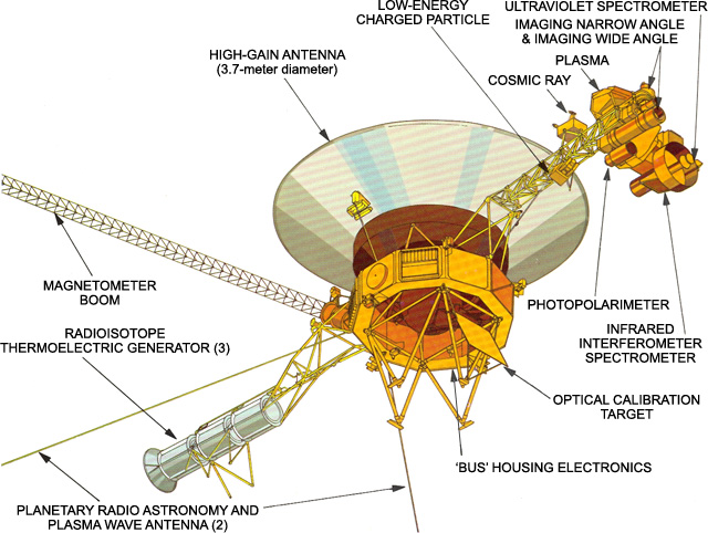
Voyager Spaceraft Instruments
(click image to enlarge)
(Source:
Spacecraft,
NASA.)
(The
Spacecraft
page also has a 3-D computer model of the spacecraft with the full-length
magnetometer boom. The two whip antennas should be ¾ the length
of the magnetometer boom, but they look shorter in the model.)
The booms and antennas have to be accounted for in attitude control
calculations:
One difference between Voyager and Mariner and Viking is that the
latter two were fairly rigid in construction. Voyager's radioisotope
thermoelectric generators, however, were mounted on a boom to keep
radiation leakage away from scientific instruments. In addition, the
magnetometer was boom mounted to avoid interference from spacecraft
magnetic fields caused by motors, actuators, power buses, and electronics.
Finally, the scan platform was also on a boom to give a better field of
view. The extended booms made Voyager much less rigid in flight, with
thruster firings and maneuvers causing the booms to flex, complicating the
attitude control problem. Additionally, the Titan III booster used for
Voyager required a "kick stage" to successfully inject Voyager into the
transfer orbit to Jupiter. Since the kick stage was kept simple, the
spacecraft itself was required to do attitude control during firing,
which entailed much narrower margins of control than the three-axis
pointing in cruise.
James E. Tomayko,
Computers in Spaceflight: The NASA Experience, 1988
Chapter
Six, Section 2, p. 177.
Furthermore, Voyager's attitude control system also had to control the
scan platform (e.g., to aim the cameras)—the "articulation" part
of the AACS name. Fixed electronics were not enough and a computer was
needed, preferably a fast one. HYPACE? Not quite:
JPL's Guidance and Control Section wanted to use a version of HYPACE as the
computer for the Voyager. However, there was considerable pressure to
build on the past and use existing equipment. [Edward] Greenberg proposed
using the same Viking computer in all systems on the Voyager spacecraft
that needed one. A study showed that the attitude control system could
use the CCS computer, but the Flight Data System could not due to high I/O
requirements. Wayne Kohl, the Viking computer Cog Engineer, thought that
the Voyager project could save $300,000 by using the Viking machine for the
attitude control function. His division chief, John Scull, supported that
idea, possibly because of budget pressure from NASA. Raymond L. Heacock,
as Spacecraft Systems Manager in the Voyager Project Office, and others
from that organization were the key personnel involved in making the final
decision, influenced by the economy and feasibility of the idea. Money
could be saved in two ways by using the existing system: avoidance of new
development costs and retraining of personnel.
Guidance and Control grudgingly accepted the CCS computer on the condition
it be speeded up. Requirements for active control during the kick stage
burn meant that real-time control programs would have to be written to
operate within a 20-millisecond cycle, roughly three times faster than the
command computer. An executive for the attitude control computer differed
in nature from those for either the command computer or the Flight Data
System computer. Basically, the attitude control computer needed to run
subprograms at different rates, requiring several cycles, as in Apollo,
Skylab, and the Shuttle. Guidance and Control asked for a 1-megahertz
clock speed but wound up getting about three quarters of that. The
attitude control engineers also added the index registers that proved so
useful during the HYPACE experiment. Documentation for the system still
refers to the attitude control computer as HYPACE, even though its heart
was the command computer. General Electric, which built the command
computer, naturally built HYPACE, but the rest of the attitude control
system was constructed by Martin-Marietta Corporation in Denver.
James E. Tomayko,
Computers in Spaceflight: The NASA Experience, 1988
Chapter
Six, Section 2, pp. 177-178.
So, instead of an actual HYPACE processor, a faster, modified CCS CPU was
chosen for Voyager's attitude control system. I have not been able to learn
the extent of the modifications other than that the index register was added.
Which has made me wonder: Were the changes extensive enough to require a new
assembly language and assembler or does the AACS use the CCS assembly language
and assembler (or variants of them)?
With respect to HYPACE (and repeating Smith and Kopf), Dr. Tomayko wrote:
Index registering meant that the same block of code could be used for all
three axes, reducing memory requirements.
James E. Tomayko,
Computers in Spaceflight: The NASA Experience, 1988
Chapter
Six, Section 2, p. 177.
This sounds like the typical use of an index register: add the value in the
index register to addresses when accessing memory. By changing the value
in the index register, a program can switch between each axis's set of
variables prior to calling a common subroutine. (The three axes are
roll, pitch, and yaw.)
I suspected a simple way of implementing an index register so as to avoid
changing the CPU's instruction set would have been to place a
memory-addressable chip or electronic circuit between the CPU and memory
to hold the index value. The following description of the AACS computer
found elsewhere gives a name to a circuit that may or may not be such an
implementation:
The Attitude and Articulation Control Subsystem used an augmented version
of the CCS computer that inserted a unit (the Hybrid Buffer Interface
Circuit (HYBIC)) between the CPU and RAM, which intercepted instructions to
add indexed addressing capability (at the expense of other instructions),
and accelerated instructions that used idle cycles.
—John Culver,
"The CPUs of
Spacecraft Computers in Space", The CPU Shack.
Unlike other (incorrect) descriptions, Culver's doesn't conflate the AACS
with HYPACE, so I think he knows what he's talking about. His description
does seem to indicate that changes were made to the CCS CPU and
its instruction set for the AACS. Strangely, Tomayko's report doesn't
mention HYBIC at all.
In her 2016 paper, Matsumoto describes a problem in a decidedly more complex
HYBIC:
The Hybrid Buffer Interface Circuits (HYBIC) on V1 was switched to the
backup unit in 2002 due to a failing component inside the HYBIC Analog
to Digital (A/D) converter. The star tracker on the original HYBIC was
performing well at the time of the switch but each HYBIC has a unit
(A/D converter, sun sensor, and star tracker) dedicated to the HYBIC.
The star tracker on the current HYBIC is degrading rather rapidly and
closely monitored; it is quite likely that a HYBIC switch back to the
original is needed before the end of the mission
Sun Kang Matsumoto,
"Voyager
Interstellar Mission: Challenges of Flying a Very Old Spacecraft on
a Very Long Mission" (PDF), 2016
p. 3, 2016 SpaceOps Conference, Daejeon, Korea.
Okay, HYBIC is a lot more than just an index register or registers. (See
the picture of the
HYBIC
Logic Subassembly at the Smithsonian.) A 2006 JPL presentation about the
Voyager 2 HYBIC problems included a functional block diagram of
the AACS (click image to enlarge):
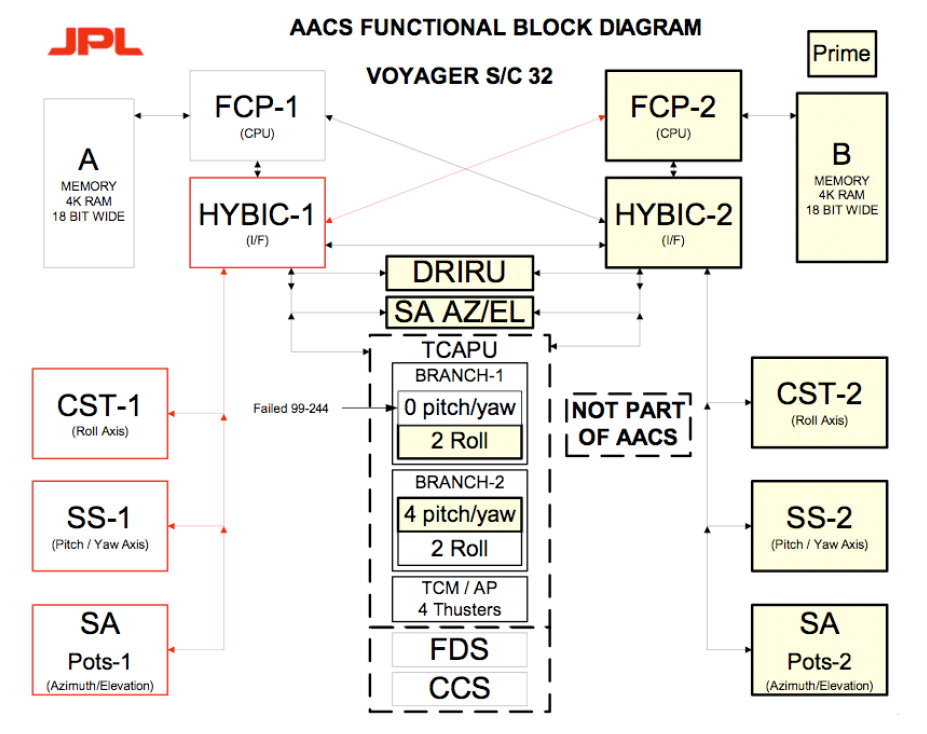
The diagram doesn't show an interface between the HYBIC and its associated
memory bank. However, a 1981 U.S. Air Force study,
Assessment of Autonomous Options for the DSCS III
Satellite System, has a similar diagram (Figure B-3, p. 178) that
adds a 6th arrow between the HYBIC and RAM. And, interestingly, has a dashed
box labeled "HYPACE" around the upper portion of the diagram!
The role of HYBIC in the AACS is up in the air for me. Online information
about HYBIC is extremely scarce and what little I could find is basically
a rehash in one form or another of the information above.
Flight Computer Electronics
I repeat that I am not an electronics engineer. Back in the 1970s, I did
pore over Don Lancaster's TTL Cookbook and Roger Melen's and
Harry Garland's
Understanding
CMOS Integrated Circuits. I built maybe a handful of small
circuits on a white ceramic breadboard from RadioShack, although the only
one I remember was a CMOS code-practice radio transmitter (Chapter 8,
pp. 126-127 in Melen & Garland) that could broadcast at most 10-15
feet to a pocket AM radio! I understood the digital electronics at an
abstract logic level, but not at the level of knowing I need a resistor
here and a capacitor there. I did build a
6800-based microcomputer held
together by duct tape and, initially, rubber bands. Slightly more
recently, in 1984-1985, I wrote the
core firmware for 80286 single-board
computers mounted in racks that tested MILSTAR satellite components.
CCS Computer
The CCS computer was built using transistor-transistor logic
(TTL)
integrated circuits:
To control development costs, the CCS is nearly identical to the embedded
computer developed for the Viking spacecraft that went to Mars, with the
addition of interface ports for the FDS and AACS. The CCS is constructed
entirely of TTL logic chips, because that's how things were done in the
early 1970s; [i]t was the heyday of the 7400 series TTL family, which was
dominated by Texas Instruments. The paired CCS computers use
dual-redundant plated-wire read/write memory, which works like
magnetic-core memory but uses wire plated with a magnetic coating instead
of ferrite beads.
—Leibson, Steven,
"Voyagers
1 and 2 Take Embedded Computers into Interstellar Space",
EE Journal, July 25, 2022.
The 7400
series of chips (labeled SN74xx) ranged from discrete logic gates to
larger-scale devices such as a 4-bit arithmetic logic unit. Strictly
speaking, Leibson is not definitively stating that the CCS was built from
7400-series chips, just that they were widely used at the time. If this
family of chips was used for the CCS computers, the actual chips used
would probably have been the military-grade versions (SN54xx) with
an extended range of operating temperatures or the radiation-hardened
versions (RSN54xx)
(Wikipedia).
Since a number of the 7400 chips like the ALU operated on 4-bit values,
I wonder why the original Viking Orbiter's CCS word size was 18 bits rather
than 16 or 20 bits. (The Viking Lander computer's word size was 24 bits;
see Tomayko, Chapter 5, Section 6.)
All that being said, I overlooked an important clue about the TTL chips in
Tomayko's account (p. 182) of the development of the
FDS computer:
[This web page] mentions the use of 54 series TTL chips in the CCS
and AACS computers. I suspect they used 54L (low power) and 54LS (low
power Schottky) TTL series chips. 54L uses about 10 times less power than
standard 54 series chips, but is about four times slower. 54LS uses about
5 times less power than 54 series, but is about 50% faster.
"Uniquely, Wooddell began working with a programmer in 1973, as soon as
the instructions were ready. Richard J. Rice of JPL began by developing
software for a breadboard version of the data computer. The breadboard
originally used the ubiquitous 4K memory of plated wire with 18-bit words
and 150 of the same low-power TTL ICs used in other JPL
machines. Instruction execution times for this version ranged from 12 to
24 microseconds. Rice's prototype flight program, developed on the basis
of what was then known about Voyager instrumentation and previous
experience, showed that the processor speed should be doubled."
—Steven Pietrobon,
"NASA
- Voyager 1 and 2 updates", NASASpaceflight Forum (unaffiliated with
NASA), August 29, 2024.
AACS Computer
As mentioned previously, the AACS computer is a
modified CCS computer. It has a faster CPU that achieves its speed at
the cost of increased power consumption, a precious commodity on a
spacecraft. My impression from the following (thanks to
Remes)
and other sources is that the two AACS computers are rarely powered up
at the same time:
... The AACS employs the same type of processors (and memories) as does
the CCS but operating three times as fast.
... Emphasis on minimizing spacecraft power consumption resulted in a
design which permitted powering only one processor (and memory) for
attitude control at a time. The backup memory may be energized for
read/write operation while the other processor provides the control
functions.
Christopher P. Jones and Thomas H. Risa,
"The Voyager
Spacecraft System Design" (abstract), 1981
p. 8, American Institute of Aeronautics and Astronautics (AIAA),
16th Annual Meeting and Technical Display
on Frontiers of Achievement, May 12-14, 1981, Long Beach, California.
(doi:10.2514/6.1981-911)
I have not been able to find out exactly which TTL chips or family of chips
were used to build the CCS and AACS computers. If the CCS
computer was built with the standard 74xx chips, the AACS computer may have
instead used the faster 74Hxx high-speed TTL chips
(radiation-hardened RSN54Hxx) or the even faster 74Sxx Schottky TTL
chips (RSN54Sxx) available at the time. (As Steven Pietrobon notes
immediately above, Voyager probably used the low-power versions of the
chips.) This is just speculation on my part and I'm sure there were other
factors that contributed to the increased speed of the AACS computer.
FDS Computer
The FDS computers were built using complementary
metal-oxide-semiconductor
(CMOS) integrated circuits:
... While the CCS and AACS computers are based on older NASA computer
designs that use plated-wire memory, the FDS computers needed much faster
memory to achieve Voyager's performance goals, so the FDS memory systems
were built with CMOS SRAMs. I asked JPL for a description or part number
of the failed SRAM and got a reply from Jeff Mellstrom, the Chief Engineer
for JPL's Astronomy and Physics Directorate. The failed device was one RCA
256x1-bit CD4061A CMOS SRAM. That one bad chip knocked out 256 words of
FDS memory.
... A report appearing in RCA's "High Reliability Integrated Circuits"
data book in 1982 stated that Voyagers 1 and 2 contained 10,346 RCA CMOS
ICs between the two spacecraft. That works out to 5173 CMOS chips per
spacecraft. Each of the dual-redundant FDS computers in each spacecraft
needed 512 CD4016A SRAMs to create the 8Kword memory, which is 1024 CMOS
SRAM chips per spacecraft. According to the reliability report, just two
of the RCA CMOS ICs out of the 10,346 total number in both Voyager
spacecraft had failed after the first 52 months in space. We know from JPL
that one of the Voyager 1 spacecraft's FDS memories failed in 1981, so at
least one of the two reported CMOS chip failures was associated with that
memory loss.
—Leibson, Steven,
"JPL
Software Update Rescues Failing Voyager 1 Spacecraft",
EE Journal, May 27, 2024.
Like the 7400 series of TTL chips, the
4000
series of CMOS ICs includes various chips that perform 4-bit operations.
For instance, the CD4008A 4-bit adder has a carry input so that four of these
can be linked together to make a 16-bit adder. I don't know if Jack Wooddell
used these particular chips or in this fashion. Tomayko's description
suggests Wooddell used a more complicated mechanism:
Despite its I/O rate, the arithmetic rate is quite slow, mostly due to
byte-serial operation. This meant 4-bit bytes are operated on in sequence.
Since the word size of the machine is 16 bits, it takes six cycles to do an
add, including housekeeping cycles. If all the arithmetic, logic and
shifting were not done in the general registers, the machine would have
been even slower.
James E. Tomayko,
Computers in Spaceflight: The NASA Experience, 1988
Chapter
Six, Section 2, Box 6-2, p. 184.
Thanks to
Remes,
we have some information about the radiation hardening of the CMOS chips:
Large quantities of CMOS devices comprising 28 different logic functions
were used in the spacecraft. Devices fabricated by the standard commercial
process could not withstand a fluence of 5 x 10¹²
e/cm2 under normal bias conditions, due to a
shift of the n-channel gate turn-on voltage toward 0 V, accompanied by an
increase in the supply current. By reducing the gate oxide annealing
temperature from 1100 to 950° C, it was found possible to fabricate
devices that were still functional after irradiation to 5 x
1012 e/cm2, though with
somewhat degraded device characteristics (References 6-1 and 6-2).
However, even these devices showed significant degradation at a dose of 150
krad(Si) ...
A CMOS static random-access memory, very susceptible to ionizing
radiation, was also used on the spacecraft,. A hardening program for
this component was considered to be too expensive. It was, therefore,
decided to apply massive shielding, so that the impinging total dose
would not exceed 10 krad(Si).
A.G. Stanley, K.E. Martin, and W.E. Price,
"Voyager
Electronic Parts Radiation Program (Volume I)" (abstract, 9MB
PDF),
pp. 6-1 and 6-2, 1977.
It's not clear to me, but is it safe to assume the "massive shielding" was
applied to the entire FDS computer and not just the memory board? And in
conjunction with the fabrication changes? An omitted paragraph about the
"degraded device characteristics" showed CMOS chip propagation delays
increasing by factors of 50% to 100% as radiation levels rose.
Leibson's second paragraph above about the reliability of CMOS chips is a
slightly incorrect interpretation of an odd table in an RCA CMOS databook.
(The PDF is a selection of pages from a larger work, whose title is not
apparent. The 1983 RCA CMOS Integrated Circuits Databook
has a chapter on high-reliability ICs, but it is much briefer than the
linked-to PDF and it does not have the information about actual military
and aerospace projects using these chips.)
Here's the odd table (click to enlarge):
52 months is not the elapsed time in space, but is instead the sum of the
"orbit times" of Voyager 1 (27 months) and Voyager 2
(25 months). One would think that time in orbit was the time in space,
but the 27-month and 25-month figures then don't make any sense.
Voyager 2 was launched a little over 2 weeks before
Voyager 1, not 2 months after! And, as of October 1980
(footnote 6 in the table), the time in space for each spacecraft was
roughly 37 months (September 1977 through September 1980), for a sum
total of 74 months. Given the October 1980 date, the two chip failures
predated the 1981 memory failure.
One would also think that device-hours was simply the orbit time in
hours multiplied by the number of devices, but the figures in the table are
that value divided by the number of spacecraft (two in Voyager's case):
orbit-time * 30 days/month * 24 hours/day * #devices
#spacecraft
I'm not sure what purpose is served by this average device-hours per
spacecraft.
Leibson's article about the CMOS chips does bring up something I hadn't
previously given any thought to — how big are the Voyager
computers? If the numbers are correct, 5,173 CMOS chips per spacecraft
is a lot, or seems so. And that works out to about 2,500 chips per FDS
computer? A fifth of those are the 512 static RAM chips making up the
computer's 8K words of memory. Throw in the address decoding circuitry,
interfaces between the FDS computer and both CCS computers, the interface
to the other FDS CPU's RAM, interfaces to external hardware such as the
Digital Tape Recorder and the science instruments, the instruction decoding
and execution circuitry, the direct memory access circuitry, etc., etc.
The numbers quickly add up.
A picture widely shown on the web as "the FDS computer" is this grainy,
black-and-white image from Tomayko's report
(cropped by me; click to enlarge):
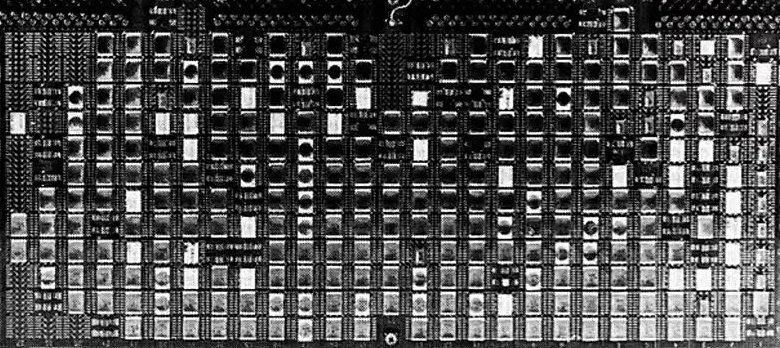
"The Flight Data System hardware in its package. (JPL photo 360-751AC)"
Board label: MJS77 FDS 2006A3A1 S/N 003
(Source: Tomayko, Chapter 6, Section 2, Figure 6-2,
p. 181)
(click image to enlarge)
(The actual hard-copy report probably had a better quality, possibly color
photograph.) If those rectangles in the image are CMOS chips, there's room
for 27 columns times 12 rows of chips, plus 2 extra chips at the top and
minus 1 chip at the bottom center — or 325 chips in total on a
circuit board. (Heacock, p. 222, has a picture of
a different but similar board with a more fully populated 27x12-chip layout.)
I've only ever worked with dual in-line package (DIP) ICs, but the only way
to fit 300-some DIP chips on a 7-inch by 14-inch circuit board (see below)
is if all the chips are 8-pin ICs. The 1975 and 1983 RCA CMOS
Integrated Circuits Databooks list only one chip with 8 pins, the
dual 2-input NAND CD40107B, and it would make no sense to build a board
filled entirely with 650 discrete NAND gates. However, a 16-lead, ceramic
flat pack (CFP) chip is about the same width and about half the length of a
16-pin DIP chip, so a 7x14-inch board will support a 27x12 layout of
16-lead CFPs. Fitting a 16-lead CFP into approximately the same space as
an 8-pin DIP is accomplished by doubling up the pin holes underneath the
chip and using a machine or jig to bend and cut the leads into the cramped
space. Looking closely at the grainy FDS board image, I think Voyager uses
a pin hole configuration similar to the following from a radar processor
board from the late 1970s:
|
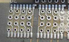
|
|
14-lead Ceramic Flat Package (Source: 1983 RCA CMOS Integrated
Circuits Databook, p. 14)
|
Mounting holes for two 16-lead CFPs on a "Westinghouse radar processor
board (70's)" (Source: Don Straney,
"Reverse-engineering
misc. avionics (ongoing)", June 5, 2024)
|
By my calculation, the number of circuit boards for a single FDS computer
would be 8 boards (if all 2,500 chips were at most 16-lead). Someone with
experience in this type of technology probably knows of techniques for more
compactly packaging the electronics, not only for the FDS computers but for
the CCS and AACS computers as well. I learned of one such technique from a
post
by Steven Pietrobon in an
online
discussion of the November 2023 FDS memory problem. The actual
semiconductor component of a chip is called the
die,
which is connected to leads/pins and encased in a CFP or DIP. By
collecting multiple dies in a single package, you reduce both the
size of a circuit and the number of external wire connections (board traces)
that would have been required between individual dies in individual CFPs or
DIPs. Voyager used this technique for the FDS memory, assembling 128 256x1
CD4016A dies into a 2K x 16-bit configuration:
Algorex Data Corporation is supplying a thick film hybrid memory circuit to
the Jet Propulsion Laboratory for use on the Mariner spacecraft, which will
be launched in 1977 to rendezvous with Jupiter and Saturn. The memory will
consist of four, 3x3 inch, four-layer hybrid circuits, each containing 2048
16-bit words. Each hybrid contains 140 chips: 128 CMOS memory chips and 12
driver chips. The memory chips are RCA CD4061 static RAMS with a 256 x 1
organization. The four hybrids do the job of two 7 x 14 inch multilayer
boards, and the cost, in the low hundred-thousand-dollar range, is
reportedly half the conventional approach.
—Dennis E. Berglund, Irving Goodman, William J. Patterson,
and Julius Reiner,
Hard
Preprocessor Study (11MB
PDF),
AFAL-TR_75-157, p. 67, 1975.
These are custom assemblies of multiple dies, not single 2Kx16-bit dies.
Voyager was originally called the
Mariner
Jupiter-Saturn 1977 (MJS77) program and was renamed "Voyager" only months
before the spacecraft launches! Rather than spreading 512 CD4061A chips
across multiple circuit boards, an FDS computer's full 8K words of memory
in four 3x3-inch modules could be mounted on one circuit board with room
to spare. I highlighted the memory modules in the following picture
(note the MJS77 label):
Also see the backplane side of the
Flight
Data Subassembly Bay. I assume the connectors shown mate on the other
side with the connectors at the top of the FDS boards.
FDS Flight Software
No source code for any of Voyager's computers—CCS, AACS, or
FDS—has been released to the public as of this time. However,
tantalizing fragments of FDS source code have been shown in several
JPL presentations. A lot can be inferred from this code about the
FDS processor's architecture and I do so here. I present and discuss
the code fragments in the chronological order of their JPL presentations.
I recommend first reading my earlier discussion
of the FDS CPU architecture. And keep Steven Pietrobon's
description
and
instruction
set compilation handy.
Some key aspects of the FDS computer to keep in mind:
8K of memory with a 4K processor - The FDS computer has 8K 16-bit
words of memory, requiring 13 address bits. The CPU can only access 4K
words (12 address bits). Consequently, the full 8K words of memory are
treated as two 4K memory banks: the lower 4K is write-protected/read-only
and the upper 4K is writable. Nominally, the write-protected lower bank
is intended for code and the writable upper bank is intended for
data/variables. Bank selection is via two independent
13th address bits that can be set by the
software, one for instruction fetches of code and the other for
reading/writing data. I don't know how strictly the
lower-bank-code/upper-bank-data convention was originally enforced,
but the available code fragments do show the software switching code
execution from one bank to the other.
128 "special registers" stored in the lower memory bank - The CPU
has three hardware registers—A, B, and C—and 128 special
registers located in the top 128 words of the lower memory bank (addresses
0F80-0FFF). The lower memory bank is write-protected, so how do you store
values in the registers? My guess is that the register-oriented
instructions are implemented such that they temporarily assert an
overriding write signal. This would allow only them to write to the
registers, while general memory-write instructions like MLD
could not write to those locations.
2.5-msec timer interrupts - The FDS software is structured around
time slots (P periods) created by a regular 2.5-msec timer
interrupt. 24 time slots constitute a cycle corresponding to an
image line from the cameras. The computer performs different processing
during each of the 24 slots and then begins the cycle anew. 800 cycles
constitute a 48-second frame, which corresponds to the 800 lines
in an image.
When a timer interrupt occurs, execution is immediately forced to address
0x0000 in the lower memory bank. The code there is effectively the
cyclic executive I discussed under
Performance Constraints. The
13th address bits are apparently reset to
the lower bank for both code and data.
As years go by, and then decades, it often happens that software tools and
documentation gradually disappear. The FDS source code could not totally
avoid that fate. David Cummings introduced the code listing for the timer
interrupt handler (below) as follows:
[W]e do not have the code, the source code in native format. This is
all we have. We have what appears to be a listing in a Microsoft Word
document, that we believe probably came from a hard copy listing that
was then scanned in an OCR. That's our theory. And it's all full of
errors and typos as you can imagine.
David Cummings,
"How We Diagnosed and Fixed the 2023 Voyager 1
Anomaly from 15 Billion Miles Away", 2025
slide/page 9 in PDF,
11:15
in video; 18th Annual Flight Software Workshop, March 25, 2025,
Seattle, Washington.
It is likely that all of the individual listings are from the Microsoft
Word document and they may or may not be the same as the code actually
running on the spacecraft. (This includes the corrupted memory block
listing, which appeared in both his and Waggoner's presentations.)
Corrupted Memory Block (2023 FDS Memory Anomaly)
The following is an abbreviated listing of actual FDS code in the 256-word
memory block (0x1400-0x14FF) that failed in Voyager 1's FDS
computer in November 2023. The code was relocated into good RAM.
The listing is from Bruce Waggoner's Saving
Voyager 1! video; see my discussion in the
November 2023 Memory Anomaly
section further down. I edited the code here to only show the pre-failure,
uncorrupted memory values; the full listing can be found in my discussion
of the memory anomaly. Note that this executable code is in the upper 4K
memory block:
13DE  1C00  GETEID: SRB  UMRA           /SAVE RETURN ADDRESS
...
1400  7829          PWD  RMFC,R2        /CALCULATE ADDRESS AND GET IDS FOR 400
...
1461  1C09  MOD15:  SRB  LMRAN          /SAVE RETURN ADDRESS
...
1469  9C40          SKP  R1             /IF DIFF IS POSITIVE USE IT
146A  9D83          ISP  SKIPPR         / NOT POSITIVE, SO DO A 4-CYCLE SKIP
146B  7820          PWD  R1,R2          / POSITIVE SO USE IT
...
146D  F09F  COPY:   OUT  7,SETAD        /SET ADDRESS DOWN
...
1494  F09F  SAFECA: OUT  7,SETAD        /SET ADDRESS DOWN
...
14B0  5F84  PLSCL:  MRD  AUTOCF         /PLS AUTO CAL FLAG
...
14BF  5BED          MRD  PLSCWB         /RESTORE NORMAL CONFIGURATION
14C0  1C31          SRB  NEWPLS
14C1  04C8          JMP  GSNOCA         /CONTINUE
...
14CA  1C08  PLSCHK: SRB  LMRA           /SAVE RETURN
...
14F0  37AF  PLSTBL: CON  $X37AF
14F1  ADFA          CON  $XADFA
14F2  FA7F          CON  $XFA7F
14F3  AFB0  PLTZ:   CON  $XAFB0         /'0' NOT USED
...
14F4  F09F  ULINK:  OUT  7,SETAD        /SET ADDRESS DOWN
...
14F8  03DE  XGETEI: JMS  GETEID         /GET ENG ID SUBROUTINE
14F9  050A          JMP  UVECTR         /RETURN TO CALLER IN LOWER MEMORY
14FA  0231  XCMROT: JMS  CMROT          /CODED COMMAND PROCESSING
14FB  050A          JMP  UVECTR         /RETURN TO CALLER IN LOWER MEMORY
14FC  02B6  XCHSUM: JMS  CHSUM          /CHECKSUM
14FD  050A          JMP  UVECTR         /RETURN TO CALLER IN LOWER MEMORY
14FE  02EF  XLTS:   JMS  LTS            /LTS SUBROUTINE
14FF  050A          JMP  UVECTR         /RETURN TO CALLER IN LOWER MEMORY
Slide 31,
23:00
in video of Bruce Waggoner, "Saving Voyager 1".
Code in green from slide/page 33 in PDF,
49:30
in video of David Cummings,
"How We Diagnosed
and Fixed the 2023 Voyager 1 Anomaly from 15 Billion Miles Away"
The code doesn't reveal much, but it does show (i) setting a
13th address bit with an OUT instruction
and (ii) the first of the two techniques for returning from a
subroutine. A key factor behind both items is that the FDS computer is
running code in upper memory. Specifically, the upper 4K memory bank is
both the code bank and the data bank. (13th
instruction address bit = 1, data address bit = 1)
Switching Code/Data Banks
The 13th address bits select which memory
banks—lower or upper—are the code and data banks. The
two independent bits are changed with OUT instructions:
    Code Bank:
    F087  OUT  7,SETJU		/SET JUMP UP
    F08F  OUT  7,SETJD		/SET JUMP DOWN (a guess!)

    Data Bank:
    F097  OUT  7,SETAU		/SET ADDRESS UP
    F09F  OUT  7,SETAD		/SET ADDRESS DOWN
SETAD first appeared in the listing above from Waggoner's presentation.
SETJU and SETAU showed up subsequently in Timer
Interrupt Handler/Executive from Cummings' presentation. SETJD is a
guess since I haven't seen an example of it yet.
When switching code banks with SETJU or SETJD, one doesn't want control
to simply switch to the same program counter offset in the new bank.
To avoid this happening, the new address bit does not take effect until
the next JMP instruction
(Pietrobon).
That JMP instruction will specify the desired location in the
new code bank at which to continue execution. The code listing under
Timer Interrupt Handler/Executive below shows
an OUT instruction immediately followed by its JMP
instruction.
Returning from a Subroutine
Recall that, when calling a subroutine, the
JMS instruction saves the return address to register B.
The address in register B can be saved as a JMP instruction
to any location in the data memory bank with an SRB instruction.
Executing the dynamically generated JMP instruction returns from
the subroutine back to the caller. Note that the JMP
instruction is saved in the data memory bank, not in the
code bank.
Executing code in the data bank is normally only possible if the code and
data banks are the same. This is the case when running the code in the
corrupted memory block, fortunately, where the upper memory bank is both
the code and data banks. With this memory configuration, executing the
JMP return can be done in either of two ways: in-line or not
in-line. For the former, the JMP instruction is saved to the end
of the subroutine, i.e., where a return-to-subroutine instruction would
normally be. When the subroutine reaches its end, the program counter is
incremented and the saved JMP instruction immediately returns to
the caller. This is true self-modifying code.
Here's an example of an in-line subroutine, FIZZBUZZ, with its own local
variable for the return address positioned at the end of the subroutine:
    FIZZBUZZ:  SRB  FBRETURN    /Save return address in local variable.
               ... apply fizz buzz algorithm to integer ...
    FBRETURN:  JMP  $X000       /Return to caller; jump target is
                                 overwritten by SRB above.
The alternate way of structuring a subroutine is to save the return
JMP to a location other than the end of the subroutine. In that
case, the last instruction in the subroutine must be a JMP to the
saved JMP instruction:
    FBRETURN:  JMP  $X000       /Return to caller; jump target is
                                 overwritten by SRB below.
    ...
    FIZZBUZZ:  SRB  FBRETURN    /Save return address in local variable.
               ... apply fizz buzz algorithm to integer ...
               JMP  FBRETURN    /Return to caller with indirect jump.
This sidesteps the opprobrium for self-modifying code at the cost of an
intermediate JMP instruction. Again, the above methods for
returning from a subroutine only work if the same memory bank is used
for code and data. (When code and data are in separate memory banks,
a different technique for returning from a subroutine is required;
see the discussion under Set CMODE from MODE.)
Back to the code listing for the corrupted memory block in upper memory ...
The fragment at the bottom beginning at XGETEI looks like a jump table,
where each entry is a JMS/JMP pair. Pietrobon
suggested,
that the table is probably used by a subroutine which saves its return address
in memory location UVECTR. Months later, however, the "RETURN TO CALLER IN
LOWER MEMORY" comment appearing every other line in the table finally
penetrated my thick skull: that subroutine in upper memory is being called
from code in lower memory. To get back to lower memory requires
a slight change to Pietrobon's suggestion. The first operation at UVECTR
must reset the 13th instruction address bit to 0
before executing the saved return address/JMP at UVECTR+1.
For example, suppose that different subroutines need to be called depending
on some processing mode (1..N). The mode could be passed to a subroutine,
VIATABLE, which indexes into the table and calls the mode-specific subroutine:
    Lower 4K of Memory

               OUT  7,SETJU     /Set 13th instruction address bit to 1.
               JMS  VIATABLE    /Call subroutine in upper memory.
    HERE:      ...

    Upper 4K of Memory

    UVECTR:    OUT  7,SETJD     /Set 13th instruction address bit to 0.
               JMP  $X000       /Return to caller in lower memory;
                                /jump target is overwritten by SRB below.
    ...
    VIATABLE:  SRB  UVECTR+1    /Save return address (HERE in lower memory)
                                /to local variable.
               ... calculate address of mode i-th entry in the table
                   and jump to that location ...
When the mode-specific subroutine called from the table finishes, it:
- JMPs to its own saved return address/JMP, which
- JMPs to the JMP UVECTR instruction in the table, which
- JMPs to UVECTR, which switches execution to lower memory and then
- steps to the saved return address/JMP in UVECTR+1, which
- JMPs back to VIATABLE's original caller in lower memory.
My head spins and my mind reels!
Timer Interrupt Handler/Executive
When a 2.5-msec timer interrupt occurs, control is immediately transferred
to address 0000 in the lower memory bank. The code at that location
basically increments the P period counter (1..24 with wrap-around), indexes
into the P table of functions to execute in specific periods, and jumps to
the new period's function:
0000  9FCF          ISZ  PCTR           /INCREMENT P-COUNTER FOR THIS P-PERIOD
0001  801F          ABS  31             /FORCE IT TO BE BETWEEN 0 AND 31
0002  93E0          AND  PCTR,R1        /INCLUSIVE BY KEEPING ONLY 5LSB
0003  9C52          SKP  CMODE          /IS LOWER MEMORY P-TABLE TO BE USED
0004  002B          JMP  GOUP           /NO
                                        /YES
0005  8009          ABS  PTAB           /GENERATE ADDRESS WITHIN PTAB TABLE
0006  900F          ADD  R1,PCTR
0007  0FC0          JMI  R1             /AND JUMP TO IT
0008  11AF  PROGID: CON  $X11AF         /PROGRAM ID
0009  0028  PTAB:   JMP  PILL           /ILLEGAL
000A  002D          JMP  P1
000B  0185          JMP  P2
...
0020  0486          JMP  P23
0021  048F          JMP  P24
0022  0028          JMP  PILL           /ILLEGAL
...
0028  91FF  PILL:   LXR  PCTR,PCTR      /RESET P-COUNTER TO 0
0029  9F86          ISZ  PILLCT         /INCREMENT ILLEGAL P-PERIOD COUNTER
002A  3FFD  PX:     WAT  4095           /WAIT FOR NEXT CLOCK-400 INTERRUPT
002B  F087  GOUP:   OUT  7,SETJU        /SET JUMP UP
002C  0000          JMP  UPINT          /JUMP TO UPPER MEMORY INTERRUPT
...
1000  F097  UPINT:  OUT  7,SETAU        /SET ADDRESS UP
Slide/page 9 in PDF,
11:15
in video of David Cummings,
"How We Diagnosed
and Fixed the 2023 Voyager 1 Anomaly from 15 Billion Miles Away"
Bounds Checking the P Period Counter
On slide/page 7 in the presentation,
7:18
in the video, Cummings describes the repeating cycle of 24 P periods. And,
with respect to the second and third instructions in the listing above, he
says, "[W]e basically do a modulo 32 on it to narrow down [the P
counter] to five bits because there's only 24 P routines." I didn't
catch this right away, but narrowing the counter down to 5 bits gives you
a cycle of 32 P periods. Where is the check for and wrap-around at 24 P
periods? The answer, oddly enough, is in the table of P period functions:
    PTAB:  JMP  PILL		/Illegal 0th entry
           JMP  P1		/Period 1
           ...
           JMP  24		/Period 24
           JMP  PILL		/Illegal 25th entry
           ...
           JMP  PILL		/Illegal 30th entry
    PILL:			/Virtual illegal 31st entry
Let's say PCTR is 0. Upon every 2.5-msec interrupt:
- PCTR is incremented to 1; the code indexes into the table and jumps to P1
- PCTR is incremented to 2; the code jumps to P2
- ... periods 3 through 23 ...
- PCTR is incremented to 24; the code jumps to P24
- PCTR is incremented to 25; the code jumps to PILL
PILL, the routine for illegal P periods, resets PCTR to 0 and apparently
waits for the next timer interrupt, upon which PCTR will be incremented to
1 and control will jump to P1, beginning the cycle anew. Interesting ...
my guess is that this technique is faster than explicitly checking that
PCTR is in the range 1..24.
But, wait! The WAT instruction in PILL appears to pause the CPU
until the next timer interrupt, thereby inserting a no-operation time slot
between the 24-slot cycles? Why not reset PCTR and immediately jump back
to 0000 so that the P24 slot is immediately followed by P1? I must be
missing something because the 48-second image frames are definitely based
on 24-slot cycles, not on 25-slot cycles.
Also, since an illegal P period is an expected occurrence every 24 periods,
what purpose is served by the illegal P-period counter, PILLCT? The
increment-and-skip-on-zero instruction, ISZ, skips the
wait-for-interrupt when PILLCT reaches its unsigned 16-bit maximum and
rolls over to zero, which happens approximately every 65 minutes. The
code then jumps up to the interrupt handler in upper memory. Strange.
Other Notes
The code listing for the timer interrupt handler adds a third jump
instruction, JMI, to the two found in the corrupted memory block
listing. The three instructions—JMP,
JMS, and JMI—are all aliases for the same CPU jump
instruction; i.e., a 4-bit opcode of 0 plus a 12-bit address. The code
beginning at address 0000 builds the 12-bit address of the current time
slot's P-table entry in register R1. With the 4 bits of zero and 12
address bits, the contents of R1 are now a jump instruction. The code then
JMIs to the jump instruction at address 0FC0, R1's memory location
in the top 128 words of memory. (I don't know what the "I" stands for,
but, on other CPUs, this might be called jumping indirectly through
a register.)
At the PILL label (address 0028), we see the old 8086's and
other CPUs' trick of
zeroing
a value by exclusive ORing the value with itself!
At the GOUP label (location 002B), execution switches from the lower memory
bank to the upper memory bank. As Pietrobon
explains,
the OUT instruction changes the 13th
instruction address bit, but the bit does not take effect until the next
jump instruction, JMP UPINT.
It looks like the ABS instruction always loads an immediate value
into register R1. In the Set CMODE from MODE
listing below, there is an ABS followed by an MLD—so
does MLD write the value in R1 out to memory?
Telemetry Mode Variables
The next code fragment defines the telemetry mode variables, MODE and CMODE:
0BE5  81C0  MODE:   CON  $B1000000111000000     /LOAD-STATE IS EL, NO PPS SAFING, ENG
                                                /MODE 7 (MODIFIED CRUISE TABLE AND
                                                /AACS MANEUVER (50) TABLE), AACS TEL
...
0FD2  FFE0  CMODE:  CON  $XFFE0                 /CURRENT MODE (IN HEX), WHERE
      0001  GS5   EQU  1                        /1 = GS-5
      0003  GS4B  EQU  3                        /3 = GS-4B PWS REPLACEMENT
      0007  GS8   EQU  7                        /7 = GS-8
      000B  PB5   EQU  11                       /B = PB-5
      000C  PB14  EQU  12                       /C = PB-14
      000F  PB15  EQU  15                       /F = PB-15
                                                /FFE0 = EL
                                                /FFE1 = EH
                                                /FFF2 = UV-5A (UV-5)
                                                /FFF3 = PB-16
                                                /FFF5 = CR-5T (AKA CR-5A)
Slide/page 10 in PDF,
15:54
in video of David Cummings,
"How We Diagnosed
and Fixed the 2023 Voyager 1 Anomaly from 15 Billion Miles Away"
MODE is stored in write-protected memory (i.e., the lower 4K bank) and is
usually modified by the CCS computer, not by the FDS software.
CMODE is the actual telemetry mode variable that the FDS software generally
references. Since you don't want to change the telemetry mode in the
middle of an image, CMODE is updated from the MODE variable at the end of
the current 48-second frame (image line 800, 24th P period).
The definition of CMODE at location 0FD2 places it in the top 128 locations
of the lower 4K bank, the range reserved for the registers. In other words,
CMODE is a register and can thus be read/written using register-oriented
instructions executing in either memory bank. Likewise, CMODE can
only be accessed with register-oriented instructions and not with
general memory instructions like MRD and MLD (unless you
have selected the lower memory bank as the data bank).
Set CMODE from MODE
As stated immediately above, CMODE is updated from the MODE variable at the
end of the current 48-second frame (image line 800, 24th P period). Here
is the subroutine, SETMO, that does so:
053C  1C08  SETMO:  SRB  LMRA           /SAVE RETURN ADDRESS
053D  9B20          SLC  800            /IS LINE COUNTER AT 800
053E  0543          JMP  SETMOA         /YES
                                        /NO
053F  8000          ABS  0              /RESET SKIPPR HERE BECAUSE IT IS A
0540  4F83          MLD  SKIPPR         /CONVENIENT TIME TO DO IT
0541  305D          WAT  95             /EQUALIZE TIME WITH L800 PATH
0542  2C08          EXC  LMRA           /RETURN
                                        /LINE COUNTER IS AT 800
0543  5BE5  SETMOA: MRD  MODE           /GET MODE WORD FOR UPCOMING 48 SECONDS
...
Slide/page 11 in PDF,
16:53
in video of David Cummings,
"How We Diagnosed
and Fixed the 2023 Voyager 1 Anomaly from 15 Billion Miles Away"
Returning from a Subroutine
When a subroutine is called with JMP or one of its aliases, the
return address is stored in register B. An SRB instruction in the
subroutine saves the return address in register B to a memory location (in
the data bank) as a dynamically generated JMP instruction.
One technique for returning from a subroutine was
shown earlier: jump to or execute in-line the
saved return address/JMP instruction. However, this only works if
the code and data are in the same 4K memory bank. If they are in different
banks, JMPing in the code bank to a saved return address/JMP
in the data bank doesn't work—you can't do an instruction fetch from
the data bank.
Another technique is needed when the code and data banks are separate.
You can't do an instruction fetch from the data bank, but you can do
a memory read from it. The EXC operation at 0542 apparently
does such a read, loading the SRB-saved return address from location
LMRA and executing it as an instruction.
This technique can also be used when the code and data banks are the same
bank, but there might be a slight performance penalty in doing so. The
EXC instruction takes two cycles
(Pietrobon),
to which I assume you have to add the cycles for the instruction being
executed. (Okay, JMPing to a saved return address/JMP
also imposes a 2-cycle penalty!)
Both IBM 360 and Univac 1100-series mainframes had similar
EX
instructions that remotely execute other instructions in order to avoid
self-modifying code. Both had an added feature of performing a bitwise OR
of an 8-bit value with a portion of the target instruction before executing
it (and without modifying the target instruction). The typical example for
either mainframe family was changing the length field in a "move" instruction.
Woodell would have had access to IBM 360s and Univac 1100s at JPL and I
wonder if he borrowed the idea for his EXC from their
EXs.
Other Notes
The SLC instruction at address 053D is a conditional skip instruction that
tests if the image-line counter has reached 800; i.e., the 48-second mark.
This suggests that one of the CPU's 128 registers is dedicated to counting
image lines and the SLC instruction is hard-coded to only reference that
register.
I originally thought that, when a timer interrupt occurs, the code bank was
reset to the read-only, lower 4K memory bank and the data bank was reset to
the writable, upper memory bank. However, the memory read at label
SETMOA (address 0543 in the listing) of the MODE variable gave me pause.
MODE is in lower memory (address 0BE5), so MRDing it must mean
that the data bank was bound to the lower memory bank, right? Is the timer
interrupt forcing both the code and data banks to the lower 4K memory bank;
i.e., the hardware resets both 13th bits to 0?
And how does SRB LMRA write to read-only memory? Also, the SETMO
code is in lower memory beginning at 053C and, since the code and data banks
are the same bank, there is no need to use an EXC instruction instead
of a JMP to return from the subroutine. I'm very confused and I need
much more information!
FDS Image Compression
This is my attempt at understanding Voyager's image compression
implementation. Those with the mathematical knowledge to
understand compression algorithms should skip straight to
Urban's paper.
The distances of planets are increasingly large as you move from the inner
to the outer planets and that greatly weakens the power of radio signals
transmitted between the Earth and spacecraft. The following table shows
the distances of four planets when Voyager 2 flew by them. An
astronomical unit (AU) is the average distance of the Earth from the
Sun, which is about 93 million miles. Earth has a nearly circular orbit,
so the distance between the Earth and a planet at a given time can vary as
much as 2 AU depending on whether the Earth is on the near or far side of
the Sun from the planet.
Voyager 2 Planetary Encounters
| Planet |
Closest Approach |
Distance from Sun (AU) |
Distance from Earth (AU) |
| Jupiter |
July 9, 1979 |
5.33 |
6.21 |
| Saturn |
August 26, 1981 |
9.60 |
10.41 |
| Uranus |
January 24, 1986 |
19.12 |
19.83 |
| Neptune |
August 25, 1989 |
30.21 |
29.58 |
From Chris Peat's
Heavens Above;
you can enter dates at the bottom of the page.
The important thing about the distances in the table above are the rough
ratios. At the dates of Voyager 2's encounters, Uranus was
over three times as far from Earth as Jupiter had been and Neptune was
almost five times as far. As radio signals get weaker, the supportable
data rates drop. Thanks to advancing radio technology on the ground and
configuration and software updates on the spacecraft, the "achieved maximum"
rates were better than expected based on distance alone: 115.2 kbps at Jupiter,
44.8 kbps at Saturn, 29.9 kbps at Uranus, and 21.6 kbps at Neptune. (From
Table 6-1 in Ludwig and Taylor, 2002, p. 34.
Urban's 1987 paper has different figures: a "recoverable" rate of 29.9 kbps
at Saturn and an unqualified rate of 14.4 kbps at Uranus and maybe Neptune.)
To overcome rate limitations at the Uranus and Neptune encounters, engineers
employed a few techniques, on the spacecraft and on the ground. The camera
images were a massive portion of the science and engineering data downlinked
to Earth and engineers were able to reduce the required bandwidth by
(i) using the spacecraft's
Reed-Solomon
encoder hardware to efficiently encode error correction information in the
full downlink data stream and (ii) compressing the image data. (The
Golay encoding
used at Jupiter and Saturn, was only applied to the non-image data, leaving
the downlinked image data without error correction except, I guess, through
ground processing of the raw pixels; Urban, p. 2.) Michael G. Urban's 1987
paper, "Voyager
Image Data Compression and Block Encoding" (thanks to
LouScheffer!),
discusses both techniques, but I'll only focus on image compression here.
(The success of the latter technique is dependent on the former since an
uncorrectable error can render an entire compressed image line unusable.)
Urban describes the "split-pixel compressor", FAST, used for images at Uranus
and Neptune in detail. The mathematics is beyond my abilities, but the
compression scheme is based on the differences between adjacent pixels in
an image line. For each 800-pixel line, an array of 800 differences
between pixels is constructed. (Not 799; is the first difference the
reference pixel's value?) These signed differences are mapped to 8-bit
unsigned integers:
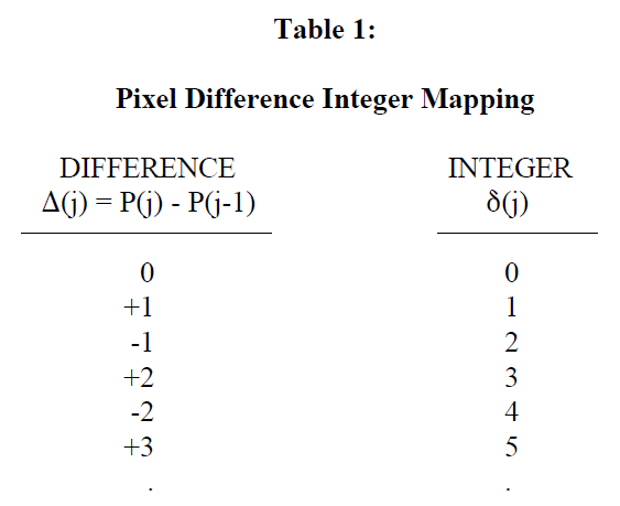
Michael G. Urban,
"Voyager
Image Data Compression and Block Encoding", 1987
Table I, p. 11,
International Telemetering Conference, October 26-29, 1987,
San Diego, California.
The 800 unsigned integers are divided into 160 5-element blocks.
Compression is then applied individually to each block. "Split pixel"
means each integer in a block is split into its k least significant
bits and its 8-k most significant bits, where k is chosen on
a per-block basis so that the 8-k MSBs are all zeroes for all 5
integers in the block. (It's the mapped unsigned integer that is split,
not the pixel value.) The value of k is encoded as a 3-bit block
ID in the compressed data:
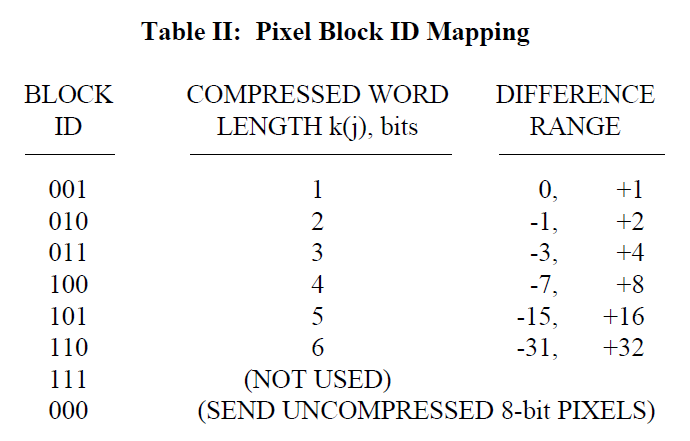
Michael G. Urban,
"Voyager
Image Data Compression and Block Encoding", 1987
Table II, p. 11,
International Telemetering Conference, October 26-29, 1987,
San Diego, California.
I noticed that for distance d, its negative, -d, can
be encoded in k bits as a two's-complement number in a range
corresponding with that in the table. Which made me wonder what the
purpose of mapping was, but I think it's because mapping groups
magnitudes together with most significant bits of zero, thus making
splitting possible. For example, in two's complement, +2 and -2 are
000010 and 111110, respectively, whereas, in the mapping scheme, they
are 000011 and 000100. Clever!
Since the 8-k bits are zeroes, it is not necessary to include those
bits in the compressed data. Note that the compressed word length is the
length of a difference's mapped, unsigned integer. If the maximum difference
in a block is outside the [-31,+32] range, all 5 pixel values are
sent as-is, not their mapped differences. (For example, a transition from
255 to 0 has a difference of -255, which maps to unsigned integer 510; this
can't be represented in 8 bits, so the raw 8-bit pixel values are sent.)
If I understand correctly, here's an example. Five uncompressed pixel
values occupy 40 bits. If the differences are in the range [-1,+2], the
compressed data is 3 bits for the block ID and 5 times 2 bits for the pixel
differences' mapped integers, or 13 bits. Nice! Differences outside the
[-31,+32] range, however, require 3 bits for the 000 block ID and 40 bits
for the raw pixel values, an undesired increase in size over simply sending
uncompressed pixel values without a block ID.
If there are too many 000 blocks with uncompressed pixel values, it is
possible for a compressed image line to exceed the space alloted for it in
the downlink telemetry frame. Rather than simply truncating each image
line on the right, compression is applied left-to-right and right-to-left
on alternating lines, the truncation on either side producing a ragged edge
on both sides. A missing pixel can be interpolated from the
corresponding pixels in the preceding and succeeding lines.
Incidentally, the downlink image/telemetry minor frame had the
following format (Urban, p. 9 and Figure 12, p. 17):
    Bytes 0-3    32-bit frame sync code
          4-4    8 zero bits
          5-5    8-bit format ID
        6-275    2160 bits of GS&E non-image science and engineering data
      276-277    16 bits of fill
                 4960 bits of compressed image data:
      278-278        8-bit reference pixel
      279-587        2472 bits for image line N (left-to-right)
      588-588        8-bit reference pixel
      589-897        2472 bits for image line N+1 (right-to-left)
     898-1025    1024 bits for Reed-Solomon code block
    1026-1079    432 bits of indeterminate value to fill out MNF to 14.4 kb/s
                -------
        Total:   8,640 bits (1,080 bytes)
At 14.4 kbps, that's one minor frame every 0.6 seconds. Some spacecraft
group repeating cycles of minor frames into major frames, but they
usually include a minor frame counter in the minor frame in addition to a
format or mode ID, so I doubt that Voyager was using major frames in this
particular image/telemetry case.
FDS Memory Problems
Just a note: I haven't heard of any problems with the CCS and AACS
computers' plated-wire memory. There was a potential
corrosion problem found and fixed before launch; see JPL's
Voyager CCS Document
Collection (Box 45, folders 454-459).
November 2023 Memory Anomaly
Significant events in the lives of the Voyager spacecraft always generate
a flurry of articles and discussions on tech sites around the web. In
November 2023, Voyager 1 began returning gibberish to Earth
instead of the normal, properly structured and formatted science and
engineering data. Through an amazing piece of detective work, the
ground team eventually pinpointed the cause: one of those CD4016A
static RAM dies had failed in the FDS memory. The die was one of
16 that made up a 256-word memory block, a block which contained code.
The following NASA blog post about tracking down the cause of the failure
was widely referenced in stories from major news outlets and in many other
online articles:
(Paragraphs rearranged in chronological order by me.)
... a command sent to Voyager 1 on March 1. Called a "poke" by the team,
the command is meant to gently prompt the FDS to try different sequences
in its software package in case the issue could be resolved by going
around a corrupted section ...
On March 3, the Voyager mission team saw activity from one section of the
FDS that differed from the rest of the computer's unreadable data stream.
The new signal was still not in the format used by Voyager 1 when the FDS
is working properly, so the team wasn't initially sure what to make of it.
But an engineer with the agency's Deep Space Network, which operates the
radio antennas that communicate with both Voyagers and other spacecraft
traveling to the Moon and beyond, was able to decode the new signal and
found that it contains a readout of the entire FDS memory.
—Denise Hill,
"NASA
Engineers Make Progress Toward Understanding Voyager 1 Issue",
NASA The Sun Spot Blog, March 13, 2024.
A media relations person at NASA, Hill probably wrote the blog post
after talking with someone at JPL, so I imagine there was a bit of a
telephone game
taking place as the story got filtered from the engineers through multiple
layers to the blog. The technical details are sketchy, so I have to wonder
if the DSN engineer really just found seemingly by happenstance that the
signal contained a memory dump (which the spacecraft just happened to send
out of the blue). It seems more likely to me that a memory dump command
was sent to Voyager 1 and, two days later, the engineers
looked specifically for a memory dump in the signal. And is there really
a "poke" command or was someone in the communication path simply trying to
describe what the engineers were doing as poking around in the innards of
the FDS? (Andrew O'Dea was the DSN engineer who decoded the data, which
the Voyager team recognized as FDS object code and thus a memory readout;
see Cummings, 2025.)
As it turns out, I was more or less wrong about an explicit memory dump
command and I was more or less right about there being no "poke" command.
In a Reddit Ask Me Anything (AMA) discussion of Voyager, Robert Rasmussen
provided a more detailed description of how the problem was diagnosed:
Although it carried no data, the radio signals we were receiving (carrier
and subcarrier) were at the expected frequencies. This told us that the
radio was probably working, that attitude control was keeping the high gain
antenna pointed at Earth, and that normal power was apparently available to
spacecraft subsystems. A repeating 1/0 modulation on the subcarrier told
us that the telemetry modulation unit (responsible for inserting telemetry
data into the radio signal) was also probably working, but that its
convolutional encoder was getting no input from the flight data subsystem
(which collects and packages the data before it's sent to Earth).
We could also tell that commands to the spacecraft were being accepted and
processed, because we were able to command Voyager 1 to make observable
state changes to the radio signal it was sending us, such as the subcarrier
frequency and modulation index.
Given that information, we decided to focus our efforts on the flight data
subsystem, trying to command it into different states. After resets and
hardware variations resulted in no improvement, and commands to its
software were not accepted, we decided to write directly to memory in the
flight data subsystem computer to see whether we could directly alter the
software's behavior. Our goal at that point had been to force a different
telemetry mode (governing contents and data rate) on the suspicion that
memory corruption might be at fault, but that some modes might be
unaffected.
After multiple attempts, that was eventually successful, but in a
surprising way, producing data in a raw format that we did not immediately
recognize. With ground system software we were eventually able to decode
this signal, revealing it [to] be just an unformatted stream of flight
data subsystem memory contents. Apparently, our memory poking had
prompted direct memory access hardware to copy memory contents to the
telemetry modulation unit port. This data revealed the corrupted area
in the flight data subsystem's memory, which we could correlate with a
particular memory chip. -[Robert Rasmussen]
—Reddit
AskScience
AMA Series: We're the team that fixed NASA's Voyager 1 spacecraft and
keeps both Voyagers flying. Ask us anything!, July 16, 2024.
(Question
and reply)
I'm still not convinced that the computer just randomly began copying its
memory to the telemetry modulation unit (TMU). And while there may be a
"poke" command in the sense of the primitive memory
peek and poke
functions some of us might remember from our microcomputer BASIC days,
there is apparently no "poke" command that performs higher-level testing
and debugging operations, a belief other authors inferred from Denise Hill's
NASA post. (Also see
Waggoner,
21:32. "So we decided to use hardware pokes ... 20 pokes for each
of the 10 modes", a technique they considered dangerous but necessary
since nothing else had worked.)
Rasmussen's reply on Reddit does hint at an answer to a question I
asked earlier: how are software/data updates
received from the ground routed to and stored in the target CPU's RAM?
In Rasmussen's description, I assume that the CCS computer, as the command
processor, is directly poking values into the FDS RAM. (Which brings up
another question! Since the CCS computer processes uplinked commands and
data, are uplink frames structured in 18-bit units or 8-bit bytes?)
What happened when the FDS computer executed code in the memory block
with the failed bit? If the failed bit was in the opcode portion of
instructions, the CPU would execute an incoherent sequence of unintended
instructions. If the failed bit was in the arguments portion of
instructions, the CPU would execute a coherent sequence of instructions
with bad arguments. Of particular concern would be branches and memory
references to bad addresses (wrong addresses, not invalid addresses).
In either case of the failed bit position, the CPU very likely went off
into never-never land. The next timer interrupt (per
Tomayko) would jerk the CPU back to reality, in which it would stay
until it next executed code in the bad memory block. I wonder if the
flight software engineers could have taken advantage of the timer
interrupt to force the CPU to copy memory to the TMU port; i.e.,
overlay or redirect the interrupt handler (at address zero
per Tomayko) to copy the memory to the TMU port.
Bruce Waggoner, Voyager's Mission Assurance Manager, added more details in
a talk at !!Con 2024 (Bang Bang Con). (The following text is based on the
video captions; any awkwardness in the text is not apparent in Waggoner's
speaking, which flows very naturally.)
(22:48)
So the DSN — it's worth a paper in itself — the DSN
figured out this amazing way to decode this data and give us what the data
represented. And it turns out it represented something really cool. This
was an accidental memory dump!
... Somehow it just said... I'm gonna read memory. And it was sending us
memory dump, completely free ... We basically could see the whole memory
and we noticed immediately that there were 256 contiguous words, 0x1400 to
0x14FF, that were corrupted or had the potential to be corrupted. And
these were all unfortunately in that layer of code under the P tables,
routines used by every piece of the FDS, basically.
Bruce Waggoner,
"Saving Voyager 1! -
Bruce Waggoner at !!Con 2024" (YouTube), 2024
!!Con 2024, August 25, 2024, Santa Cruz, California.
(The P tables bring to mind the FDS real-time executive's
P periods; perhaps they're related.)
The JPL engineers now had a readout of the FDS memory. Fortunately,
periodic full memory dumps of all the Voyager computers is standard
practice (Matsumoto, p. 7) — at 40
bits per second, about the same speed as my ham-radio brother's surplus
Baudot teletype back in the 1970s! Still, that's only an hour to
download the full 8K words of memory from an FDS computer 15 billion
miles away. By comparing the new memory dump to the last good memory
dump, it would have been relatively easy for the JPL team to figure out
which memory block(s) had failed, at least in the code portions of memory.
This task was made even easier by the fact that JPL had been loath to make
changes to the FDS flight software (Matsumoto, p. 6).
One of Waggoner's transparencies has an abridged assembly language listing
for the failed 0x1400-0x14FF memory block:
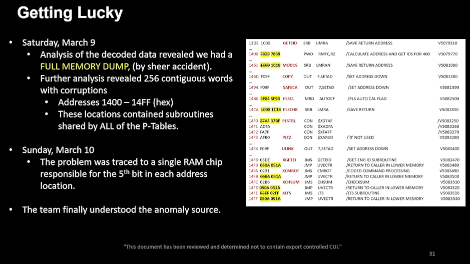
FDS Assembly Listing, Slide 31
(click image to enlarge)
from Bruce Waggoner,
"Saving Voyager
1!" (YouTube,
23:00), !!Con 2024.
And below is the listing by itself. The fifth bit in each location of the
failed memory block is read as 1 by the CPU, which is incorrect if the bit
is supposed to be 0. In the listing, memory words in which the fifth bit
is flipped are highlighted in yellow, with the correct value struck through
on the left and the corrupted value on the right:
13DE  1C00       GETEID:  SRB  UMRA       /SAVE RETURN ADDRESS
...
1400  7829 7839           PWD  RMFC,R2    /CALCULATE ADDRESS AND GET IDS FOR 400
...
1461  1C09 1C19  MOD15:   SRB  LMRAN      /SAVE RETURN ADDRESS
...
146D  F09F       COPY:    OUT  7,SETAD    /SET ADDRESS DOWN
...
1494  F09F       SAFECA:  OUT  7,SETAD    /SET ADDRESS DOWN
...
14B0  5F84 5F94  PLSCL:   MRD  AUTOCF     /PLS AUTO CAL FLAG
...
14CA  1C08 1C18  PLSCHK:  SRB  LMRA       /SAVE RETURN
...
14F0  37AF 37BF  PLSTBL:  CON  $X37AF
14F1  ADFA                CON  $XADFA
14F2  FA7F                CON  $XFA7F
14F3  AFB0       PLTZ:    CON  $XAFB0     /'0' NOT USED
...
14F4  F09F       ULINK:   OUT  7,SETAD    /SET ADDRESS DOWN
...
14F8  03DE       XGETEI:  JMS  GETEID     /GET ENG ID SUBROUTINE
14F9  050A 051A           JMP  UVECTR     /RETURN TO CALLER IN LOWER MEMORY
14FA  0231       XCMROT:  JMS  CMROT      /CODED COMMAND PROCESSING
14FB  050A 051A           JMP  UVECTR     /RETURN TO CALLER IN LOWER MEMORY
14FC  02B6       XCHSUM:  JMS  CHSUM      /CHECKSUM
14FD  050A 051A           JMP  UVECTR     /RETURN TO CALLER IN LOWER MEMORY
14FE  02EF 02FF  XLTS:    JMS  LTS        /LTS SUBROUTINE
14FF  050A 051A           JMP  UVECTR     /RETURN TO CALLER IN LOWER MEMORY
(Also see my discussion of the FDS CPU under
Why Assembly? and a detailed
exploration of this code listing under FDS
Flight Software.)
Obviously, the code in the failed memory block needs to be moved. If a
code sequence spans the beginning of the failed block, then the preceding
code must be moved as well. This, in fact, was the case with the GETEID
subroutine, which extended from 13DE to 1460
(Cummings, 2025, slide/page 24 in PDF,
36:59
in video). A code sequence at the end of the failed block could be
handled by appending a jump instruction to the block in its new location.
If a data/instruction table spanned one of the boundaries, the entire table
would have to be moved, not just the portion in the failed block. Finally,
any references to locations in the moved code/data must be patched with the
new addresses:
Once we narrowed it down to 256 consecutive locations of memory
that were corrupted
(as
we talked about here), we then examined the source code
to see what was contained in those 256 consecutive locations.
As
discussed in another answer, those locations contained a number of
subroutines used (called) in many places throughout the rest of the
flight software. Those were critical subroutines.
Therefore, the only viable solution was to try to find available portions
of memory elsewhere and move those subroutines to those other available
locations. There was not a single available chunk of memory that was large
enough to accommodate all of those subroutines (256 words), so we had to
break up the subroutines into pieces and move them to whatever small chunks
of available memory we could find and then insert jump instructions between
those broken-up portions.
(EDIT: We also had to fix up any internal jumps within each relocated piece
to account for the fact that the jump destination addresses had changed.
Then we had to identify all the callers of those subroutines and modify
each one to point it to the new (relocated) start of each subroutine.)
-[David Cummings]
—Reddit
AskScience
AMA Series: We're the team that fixed NASA's Voyager 1 spacecraft and
keeps both Voyagers flying. Ask us anything!, July 16, 2024.
(Question
and reply)
Regarding Cummings' last paragraph, including relative branch instructions
in the FDS CPU's instruction set would have made little sense. Given the
limited address space, there would have been no savings in code storage
since there is not much difference between an address and an offset.
Adding a program-counter-plus-offset adder would have greatly increased the
complexity of the electronics and probably would have had a serious impact
on performance.
Waggoner, of course, adds many interesting details. Rather than quote his
whole presentation, I want to take note of two points. First, the team had
to ensure any changes they made did not violate timing constraints in FDS
processing. Waggoner gives an example of wanting to relocate some of the
code in the failed memory block to lower memory, but doing so would have
exacted a performance penalty when switching between upper and lower memory:
I admit I'm a little confused by Waggoner's example below. Lower
memory is the lower 4K words (0x0000-0x0FFF) of the FDS computer's
full 8K of RAM; it is normally used for program code and is thus normally
write-protected. Upper memory is the upper 4K words (0x1000-0x1FFF)
of RAM; it is normally used for program data and is not write-protected.
The failed memory block, 0x1400-0x14FF, is in upper memory and
it nevertheless contained program code. So, if the code being
relocated was previously not write-protected, why would they be concerned
about it not being write-protected now?
(26:14)
Next we had to repair the codes. This is 256 instructions that had to be
relocated. We had to preserve the data of course to get our data back,
but timing was key, because every time we added a step to do the extra
jumps, it would play with the timing of the program, which could kill us.
So we understood we had to be super careful with the timing.
(28:25)
Now we have to get the science [data] back ... Again, we were out
of space ... The engineering high rate memory that we were cannibalizing
[earlier for engineering data recovery] — it was gone.
So we found an old memo from the 1980s that mentioned free memory. We
looked at the memory readouts and it looked like it was just not being
used. So we assumed it was free and went with that. This was an upper
memory and it wasn't in [a] write-protected region of memory, which was
a concern. Because we would like it to be write-protected. But if we
went to lower memory, it takes an extra step to go between high and low
memory. We were worried about the timing implications again. So we ate
the risk that we were writing to unprotected memory, and patched it on
May 18th and it worked as well.
Bruce Waggoner,
"Saving
Voyager 1! - Bruce Waggoner at !!Con 2024" (YouTube), 2024
!!Con 2024, August 25, 2024, Santa Cruz, California.
(Also see my discussions in other sections of upper/lower FDS memory in
The CPUs and of the FDS computer's general timing
requirements in Performance Constraints.)
I was surprised that memory was at such a premium.
Jones and Risa (1981, pp. 6-7) said the FDS
supported 30 science and engineering data telemetry modes; Table 2 in their
paper lists 29 modes, 10 of which are specifically for image data. After
the planetary encounters, one would expect the "retiring" of the cameras
and image handling code to free up substantial amounts of memory, but
apparently not. Two possible reasons I can think of: (i) tight
coding resulted in the code for the telemetry modes being so entangled that
it was difficult to cut out just the image handling part and (ii)
the FDS software had been patched so often over the years that it was
difficult to tell which code was still in use and which code wasn't.
Aside: See my brief discussion in the Bibliography under
Myers et al about the perils of
updating flight software via patches. Voyager was hit with three
of these pitfalls: lack of up-to-date source code, limited contiguous
free memory, and bringing in non-Voyager engineers to figure out the
software. The two engineers, Cummings
and Arslanian, did a brilliant job but decades of patches certainly
threw unnecessary obstacles in their way.
Which leads us to Waggoner's second point: the loss of FDS expertise
after 47 years left the anomaly team very unsure about how the FDS flight
software worked. Proposed changes were subject to intense scrutiny and
discussion:
(14:07)
So our top priority was to figure out what the FDS was and how it worked.
Because unfortunately the person who was the real expert had retired
decades ago and the person who was their fill-in, their backup, had
retired two years ago.
(15:43)
We had that level of uncertainty. So the only thing we could do is dig
in and research more and debate. So we had a lot of debates between our
flight team and tiger team, trying to figure out what the best thing is
to do. But ultimately, we had to suck it up and guess at some point.
And we made the right guesses, which is good.
(27:39)
So what they did is they took every possible thing that could go wrong,
they made a list and they iterated their code adjustments with that list
with multiple people. And that was essentially how they came up with
these patches.
Bruce Waggoner,
"Saving
Voyager 1! - Bruce Waggoner at !!Con 2024" (YouTube), 2024
!!Con 2024, August 25, 2024, Santa Cruz, California.
Taking 15-billion-mile baby steps, JPL limited the initial changes to those
needed to restore the handling of engineering data (spacecraft health and
status). The updated software was uplinked on April 18, 2024 and two days
later, on April 20, a normal telemetry stream was received from
Voyager 1. Naturally, a big celebration was in order; see
the image below! A month later, 2 of the 4
operating science instruments began
returning
data and, a month after that, the other 2 instruments were back online.
However, the prior functionality of the spacecraft was still not fully
restored:
While Voyager 1 is back to conducting science, additional minor work is
needed to clean up the effects of the issue. Among other tasks, engineers
will resynchronize timekeeping software in the spacecraft's three onboard
computers so they can execute commands at the right time. The team will
also perform maintenance on the digital tape recorder, which records some
data for the plasma wave instrument that is sent to Earth twice per year.
(Most of the Voyagers' science data is sent directly to Earth and not
recorded.)
—Anthony Greicius,
"Voyager
1 Returning Science Data From All Four Instruments",
NASA News, June 13, 2024.
As the recovery from Voyager 2's bit flip in 2010 showed,
this follow-on work can take months:
[W]hen the V2 experienced a bit flip in the FDS in 2010, it took about two
weeks to recover enough to receive the engineering data, and another two
weeks to receive the science data. It took another four and one-half
months to adjust the timing delay caused by the anomaly and resynchronize
the CCS and FDS clocks. Realigning the baseline events to the regular
schedule had to be delayed even longer due to other activities competing
for the resources. In the meantime, adjustments had to be made in mission
operations to compensate for this timing shift.
Sun Kang Matsumoto,
"Voyager
Interstellar Mission: Challenges of Flying a Very Old Spacecraft on
a Very Long Mission" (PDF), 2016
p. 5, 2016 SpaceOps Conference, Daejeon, Korea.
Incidentally, the flight software team gave some consideration to FDS memory
problems that potentially lie ahead:
Yes, as a result of our experiences with this anomaly, we are now in a
better position to diagnose other memory errors that may occur in the
future. We now have a small-footprint program that can be uplinked to a
small portion of memory, which will then send to the ground a full memory
read-out of all of the memory. We can use this in the future if we suspect
another memory error has struck. -[David Cummings]
—Reddit
AskScience
AMA Series: We're the team that fixed NASA's Voyager 1 spacecraft and
keeps both Voyagers flying. Ask us anything!, July 16, 2024.
(Question
and reply)
The program is called MIN MRO
(Waggoner,
25:31).
Earlier Anomalies
October 1981 — Voyager 1
The Voyager spacecraft have both experienced FDS memory anomalies in the
past. Frequent mention is made of the complete failure of one of
Voyager 1's FDS computer's memory, but details are always
lacking. I did find out the date of the failure, October 6, 1981:
The fact that all 8K words of FDS-B's memory were lost suggests that this
was not the unlikely large-scale failure of the CD4016A RAM dies, but
instead a failure of even only one chip in the interface between the
CPU and RAM, perhaps on the data or address buses. Tomayko offers a
tantalizing but confusing clue in the following quote. He is discussing
the Backup Mission Load on Voyager 2 and the complete loss
of memory in an FDS computer. However, this has never happened on
Voyager 2, only on Voyager 1. Is Tomayko
referring to the latter spacecraft's 1981 failure? (The failed chip
in the November 2023 anomaly caused a real failed bit throughout a
256-word memory block; having a failed bit in a readout register results
in a perceived failed bit throughout all 8K words of memory.)
As pioneered on Mariner X, a disaster backup sequence was stored in the
Voyager 2 CCS memory for the Uranus encounter, and later for the Neptune
encounter. Required because of the loss of redundancy after the primary
radio receiver developed an internal short, the backup sequence will
execute minimum experiment sequences and transmit data to earth; it
occupies 20% of the 4K memory. CCS programmers are studying ways to use
some bit positions in a failed Flight Data System memory to compensate for
the shortened memory in their system. A readout register in the Flight
Data System has a failed bit, giving the impression that the entire memory
has a one stored in that position in each word. Remaining "good" areas may
be assigned to the use of the CCS.
James E. Tomayko,
Computers in Spaceflight: The NASA Experience, 1988
Chapter
Six, Section 2, p. 176.
Pre-1985 — Voyager 2
At an unidentified time before this next paper was published in January 1985,
Voyager 2 lost a 256-word FDS memory block, 4 decades before
the same thing happened on Voyager 1:
On Voyager 1, as noted, one of the FDS memories has failed. On Voyager 2,
256 of the 8192 memory locations (16 bit words) have failed in one of the
memories (FDS-B). All memory locations remain intact in the other (FDS-A)
except that bit 12 at address 0F9016 is
permanently true (1).
W.I. McLaughlin and D.M. Wolff,
"Voyager Flight
Engineering: Preparing for Uranus" (abstract), 1985
pp. 5-6, American Institute of Aeronautics and Astronautics (AIAA),
23rd Aerospace Sciences Meeting, January 1985, Reno, NV.
(doi:10.2514/6.1985-287)
January 1986 — Voyager 2
Shortly before Voyager 2's January 24, 1986 encounter with
Uranus, one bit failed in one location in the secondary FDS computer's RAM.
Fortunately, this didn't totally mangle the downlink telemetry stream as
happened in the 2010 bit flip and the 2023 memory loss. Since it affected
the much needed compression of image data, the bit failure was still a
potentially serious problem with respect to the return of viable images
from Uranus (and later Neptune) to Earth.
Six days before the spacecraft's closest approach to Uranus another problem
was noted: photographs from Voyager 2 were marred by large
blocks of black and white lines. Since only compressed images displayed
the curious blotches, [a bug in the decompression software on the
ground was suspected but ruled out as the cause] ...
... After the [FDS memory] readout was received at the J.P.L., what
was in the computer's memory was compared bit by bit with what should have
been there. It was discovered that a single bit of an instruction word,
which should have been a 0, was a 1. There were two possible explanations
for the incorrect bit: either a cosmic ray had caused the bit in the memory
cell to flip from 0 to 1, in which case it could easily be reset to 0, or
there had been a permanent hardware failure in the memory.
The FDS experts at the J.P.L. were immediately directed to write a program
that could act as a patch, circumventing the possibly failed memory
location. The patch was programmed into the spacecraft's computer on the
evening of January 20, four days before the closest approach. The next
morning the transmission of fault-free compressed photographs resumed.
Although the troublesome memory location had been bypassed by the patch,
a command that could reset the incorrect bit was also transmitted to the
spacecraft. The bit did not reset, however, and is considered to have
failed permanently.
—Richard P. Laeser, William I. McLaughlin and Donna M. Wolff,
"Engineering
Voyager 2's Encounter with Uranus", Scientific American,
November 1986, pp. 44-45.
April 2010 — Voyager 2
In April 2010, Voyager 2 began sending an initially unreadable
stream of data. With a lot of effort, it was determined that a bit had
flipped in the FDS memory. The memory location was successfully reset,
but it was a months-long process to return the science handling to normal;
see the Matsumoto quote above.
Interestingly, the ground team apparently still had some FDS simulation
capabilities:
On May 12, engineers received a full memory readout from the flight data
system computer, which formats the data to send back to Earth. They
isolated the one bit in the memory that had changed, and they recreated the
effect on a computer at JPL. They found the effect agrees with data coming
down from the spacecraft. They are planning to reset the bit to its normal
state on Wednesday, May 19.
—NASA,
"Engineers
Diagnosing Voyager 2 Data System -- Update", NASA News,
May 24, 2010.
In 2010, as in 2023, the Deep Space Network (DSN) played a key role in
deciphering the mishmash of data being transmitted by the spacecraft.
I was surprised at how much mission-specific processing takes place in
the DSN ground system as opposed to the spacecraft's JPL ground system.
Remes
turned up a report about this anomaly that gives us a taste of what the
2023-2024 ground teams had to deal with:
An analysis by Steve Howard of the data received at the station shows that
telemetry frames are longer than expected by 80 bits with every fourth
frame only 60 bits longer. He compared the 26 April data with the last
data received on 21 April and found that the actual frame time was 48.46
seconds instead of the nominal 48.0 seconds (an increase by nearly a half
a second per frame, which exactly explains the 75, on average, extra bits
we are seeing in the data. He asked, and it was agreed that the station
configure a parallel string to try to process the telemetry at 158.5 bps
as well as the nominal 160 bps. During this morning's pass, 28 April,
the station configured a second Downlink Channel Controller (DCC). They
still saw the 80/60 extra bits per frame at the backup DCC. The DCC could
frame sync on those 80 bits longer but not the fourth frames. At any rate,
the AMMOS can not currently process these data.
—"Cosmic
Ray Subsystem Report on the Voyager-2 Flight Data System Anomaly and the
Subsequent Data Impact" (PDF), 2010, Appendix A, p. 8.
(The Advanced Mult-Mission Operations System,
AMMOS, is a JPL-developed, generic
"set of mission operations and data processing capabilities for robotic
missions" and, I gather, a generic term for a spacecraft's specific,
AMMOS-based ground system. These capabilities include the front-line
mission control functions as well as the off-line sequencing and analysis
tools such as SEQGEN, etc.)
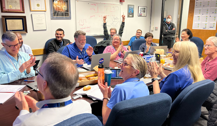
The Voyager team celebrates the successful
resumption of intelligible data transmissions from Voyager
1! In November 2023, the spacecraft began sending jumbled
data. The problem was eventually traced to a failed section of
FDS memory. The flight software team relocated the code in the
failed section elsewhere and were relieved and excited when
Voyager 1 resumed sending good data on April 20, 2024.
Near side of table, L-to-R:
Jeff Mellstrom, Suzanne Dodd, Linda Spilker, and Jim Donaldson.
Far side of table, L-to-R:
Kareem Badaruddin, Todd Barber, Jennifer Herman, and Lu Yang.
Far end of table:
Sun Matsumoto.
Seated against wall, L-R:
Joey Jefferson, Nshan Kazaryan, Dave "Goal!" Cummings,
and Armen Arslanian.
Standing in the doorway:
Bruce Waggoner.
(Source:
"NASA's
Voyager 1 Resumes Sending Engineering Updates to Earth" and
"Voyager
Team Celebrates Engineering Data Return", April 2024, JPL.)
Miscellaneous Information
Ben-Hur Rides Again!
Eat your heart out,
Lew Wallace, author
of Ben-Hur! I don't recall ever seeing the whole movie, but
I did read the novel. My memory is that the chariot scene was even more
exciting in the book than in the movie, but neither hold a candle to
Voyager 2's launch troubles!
Based on Tomayko's telling (Box 6-1, p. 179-180, in Computers in
Spaceflight), my understanding is that the Voyager 2
spacecraft had separated from the launch vehicle and was in the process
of extending the booms while at the same time trying to correct its
whopperjawed attitude. Things began to go wrong, but I'll let Rasmussen
and Litty tell the story:
The first launch provided more excitement with little delay. An
unbelievable combination of events shortly after injection initiated a
chain reaction that ultimately triggered nearly every single fault routine
in the AACS repertoire. Briefly, the sequence happended as follows.
The spark to the fuse was a partially latched boom, resulting in high
tip-off rates at propulsion module separation. Meanwhile, reconfiguration
activities and a precautionary restoration of isolation value states had
temporarily disabled attitude control. While thrusters were waiting to
fire, the tip-off effects were accumulating, so that by the time the
isovalve power requests reached the top of the queue, a large angular
offset existed. By coincidence, thruster control was re-enabled just
before sequence activation of thruster fault detection. This quickly
responded to the large error by again disabling thruster firing in
preparation for a switch to backup thrusters. More isovalve activity
ensued causing further delays, three more repetitions of the error
reponse, and finally a self-inflicted heartbeat failure, all within
sixteen seconds of separation!
This last action was pivotal in resolving the situation. The new system,
with no memory of past difficulties, including the large error, quickly
brought the rates under control. Finding the sun nowhere in sight, this
system then proceeded automatically to search for and acquire celestial
references, achieving success less than three hours after launch. Ground
operations spent the next several days recovering.
—R.D. Rasmussen and E.C. Litty,
"A Voyager Attitude
Control Perspective on Fault Tolerant Systems" (abstract), p. 246,
American Institute of Aeronautics and Astronautics (AIAA)
Guidance and Control Conference, August 19-21, 1981,
Albuquerque, New Mexico. (doi:10.2514/6.1981-1812)
That last exquisite sentence is priceless!
Suzanne Dodd: Early Voyager Years
A couple of additional paragraphs from the Caltech Heritage Project article:
DODD: It was quite a bit different. But, you come in, and it was a fairly
routine thing. You would be working on a sequence, and it would take six
weeks to develop that sequence, and then there was different steps, and
different software programs, and different reviews. That process then
repeats itself every six weeks. From a work standpoint, you're doing a
fair amount of the same thing, although you sometimes had special events.
You sometimes worked with a particular science team on a special
calibration they wanted to do. What I do remember is the Voyager team,
the sequence area had a lot of pranksters in it. They would like fill
a person's drawer with water and put fish in there, and so when they came
in the next day, the water would splash and they'd have these goldfish
swimming around in their desk. [laughs] It's that kind of a team
camaraderie. Most people would eat lunch together, too. You just
really were cohesive as a team.
ZIERLER: What areas did you have real responsibility, even in the early
years?
DODD: I hired in when four other people hired in. Now, Voyager went
through Jupiter and Saturn, and then it had a bathtub, because it had five
years to get out to Uranus. So a lot of people left. Because Jupiter and
Saturn were like 18— maybe two years apart, 18 months to two years
apart in encounters. Then there was this lull, so they had to cut—
a lot of people left, and/or they just needed to trim staffing. A bathtub
in staffing, because there was such a long duration. So, I was part of
the crew that came back in, new group of crew that came back in during
Uranus. There were four of us that hired in all at the same time, to do
basically the same job, which was sequencing. It was basically a very
junior job on Voyager, sequencing engineer, but a super exciting mission.
Really gets you going for liking this type of work. Then, when it came
to Neptune, I got to be the lead sequence engineer. So, of the four of
us that were doing it, I got the closest approach sequence.
David Zierler,
"Suzy
Dodd (BS '84), Engineer and Deep Space Pioneer", 2023
Caltech Heritage Project, June 9, 2023.
Larry Zottarelli
In an article about astrophysicists debating whether or not
Voyager 1 actually had entered interstellar space, the following
encapsulation of a CNN report on Larry Zottarelli appeared:
[Determining if Voyager 1 has really entered interstellar space] will
also be just a little bit harder than it was last week, because the last
original member of the Voyager team has retired. Larry Zottarelli,
aged 80, left NASA's employ this week after 55 years on the job.
Zottarelli helped to develop Voyager's on-board computers and has
worked on the mission since 1975. CNN reports that he was sent on
his way with a handshake from actress Nichelle Nicholls, Star Trek's
Lt. Uhura. NASA is reportedly seeking a replacement fluent in FORTRAN,
Algol and assembly language for the Voyagers' 250 KHz General Electric
18-bit TTL CPUs, complete with single register accumulator and bit-serial
access to 4096-word plated-wire RAM.
—Simon Sharwood,
"Has
Voyager 1 escaped the Sun yet? Yes, but also no, say boffins",
The Register, October 30, 2015.
Boffin is British slang for a scientist or engineer! And the original
CNN
report has pictures, especially of Zottarelli with Nichelle Nichols
AKA Lt. Uhura! (The Register gets it wrong, however. The
picture with Nichols is from the Voyager 30th anniversary celebration
in 2007, not Zottarelli's retirement.)
The following is from an (unpublished?) article about the Voyager team:
The quiet voice, that's Larry Zottarelli, the programmer and "computer
whisperer", understanding his machines like no one better does.
—Joachim J. Kehr,
Editor SpaceOps News of the
Journal of Space Operations & Communicator;
April 2016,
"Voyager —
The Right Staff" (PDF), p. 4.
I wasn't fortunate enough, but I think I would have liked working with him!
(The Kehr article includes an interview with Suzanne Dodd.)
I don't quote it here, but this widely cited, 2017 article in the New
York Times leads with a picture of and story about Larry Zottarelli:
"The
Loyal Engineers Steering NASA's Voyager Probes Across the Universe",
by Kim Tingley, New York Times, Aug. 3, 2017.
Real Programmers & Nightmare Networkers
In the early 1980s, Ed Post wrote of the non-quiche-eating Real Programmers
who make the world go round:
Some of the most awesome Real Programmers work at the Jet Propulsion
Laboratory in California. Many of them know the entire operating
system of the Pioneer and Voyager spacecraft by heart.
With a combination of large ground-based FORTRAN programs and small
spacecraft-based assembly language programs, they can do incredible
feats of navigation and improvisation, such as hitting 10-kilometer
wide windows at Saturn after six years in space, and repairing or
bypassing damaged sensor platforms, radios, and batteries. Allegedly,
one Real Programmer managed to tuck a pattern-matching program into
a few hundred bytes of unused memory in a Voyager
spacecraft that searched for, located, and photographed a new moon
of Jupiter.
—Ed Post,
"Real
Programmers Don't Use Pascal", Datamation, July 1983,
"READERS' FORUM", pp. 263-265.
(HTML version; the
full
magazine issue is available as a large PDF.)
In the 1990s, the late Peter
Fenelon of the University of York wrote a guide for spotting the different
species of academic programmers:
[The Nightmare Networker] relishes complexity. The database runs on an
IBM somewhere in Canada; the X-windows front end on a Hewlett-Packard in
Switzerland, the inference engine on a Cray in Indonesia and the program
itself on Voyager II... each part of the packages
employs different comms protocols depending upon a wide range of
factors including the phase of the moon...
—Pete Fenelon,
"Academic
Programmers - A Spotter's Guide", 1997?
Clash of Viking Mainframes
This section is not related to Voyager. While searching for information
about the Voyager flight computers, I landed on Herb Johnson's web page,
"COSMAC
1802: history of microprocessors in space", and his accompanying
notes
about the Viking flight computers. The notes rely mostly on
Tomayko's report and a Martin Marietta Corporation
report, Viking Software Data.
(The links to the report in Johnson's notes don't work anymore.)
Preceding the Voyager program by several years, the
Viking mission to
Mars began in 1968. Two identical pairs of spacecraft were launched in 1975
and arrived at Mars in 1976. Each pair consisted of (i) an
Orbiter
which went into orbit around Mars and (ii) a
Lander
which landed on Mars.
JPL was responsible for the Orbiter. Martin Marietta designed and developed
the Viking Lander and its flight software. They also developed the
ground-based, mission operations (mission control) software for the Lander.
Afterwards, Martin Marietta wrote an evaluation of the software development
process for the U.S. Air Force, the document used by Herb Johnson above.
Viking Software Data turned out to be very interesting reading.
After the introductory material, the document consists of individual
evaluations of different techniques used in the development and testing
process. Each evaluation is structured as follows: name, summary, application
considerations, recommendation, history, description, qualitative results,
and quantitative impact.
I was motivated to write "Clash of Viking Mainframes" upon being taken aback
by the description of the second technique, "DIFFERENT DEVELOPMENT/INTEGRATION
SITES". Martin Marietta developed and tested the mission operations software
on Control Data Corporation (CDC) mainframes at their Denver, Colorado
facility (denoted MMC) and then converted the source code
to be compiled and tested again on the target Univac and IBM mainframes at
JPL's Pasadena, California Viking mission control center! This is somewhat
akin to developing a native Windows application under Linux because you only
had a Linux PC; though possible, it would be unthinkable today. However, as
you'll see, there were some very good reasons for this approach —
some known beforehand and some uncovered during the process — and
I can't fault Martin Marietta or JPL for taking this approach.
NASA management feared JPL overextending itself, so it assigned the Orbiter
to JPL and the Lander to Martin Marietta. However, the Lander integration
and test and the actual operations would still take place at JPL. So:
Martin-Marietta Corporation, the Viking Lander contractors, had to do some
dangerously unique software development when NASA decided to move control
of the Lander from Langley to JPL. Since Orbiter software development and
giving support to other missions tied up JPL's computers, Martin took the
chance of developing the Lander software in a "minimal higher order
language," specifically a hopefully transportable subset of FORTRAN.
Martin's solution reflected its recent migration to IBM 370 series and
Control Data 6500 series computers at its Denver plant. These were
technologically more advanced than the JPL computers and could not be
trusted to produce directly transportable software. The idea worked, but
Martin admitted that the requirement for delivering mission support
software 10 months before the flight provided strong motivation.
James E. Tomayko,
Computers in Spaceflight: The NASA Experience, 1988
Chapter
Eight, Section 3 (Unmanned mission control computers), p. 267.
And getting into the "DIFFERENT DEVELOPMENT/INTEGRATION SITES":
APPLICATION CONSIDERATIONS: The forecasts for the loads on the computer
sets at JPL indicated that the MMC portions of the Viking operational
software system could not be developed on them. The MMC facility contained
CDC 6400, CDC 6500 and IBM 360/75 computer sets, whereas the JPL facility
contained UNIVAC 1108 and IBM 360/75 computer sets. The operating systems
of the IBM computers at the two facilities were different. No equipment
similar to the JPL UNIVAC 1108 system was available in the Denver area.
Pathfinder studies indicated software could be developed on non-target
computers without creating any serious conversion problems.
(p. 30)
HISTORY: One of the problems which faced the management of the Viking
mission operations lander software development was that the development
computers differed from the operational computers. The Martin Marietta
facility consisted of CDC 6400 and CDC 6500 and IBM 360/75 whereas the JPL
computer facility consisted of IBM 360/75s and UNIVAC 1108s. Thus the
software conversion task became a management concern very early in the
software development activities. (p. 31)
Martin Marietta Corporation,
Viking
Software Data: Final Technical Report (15MB PDF)
, 1977
May 1977, RADC-TR-77-168.
Keep in mind that lacking the target Univac mainframe could not be remedied
by running down to the local computer store, picking a computer off the rack,
and then shoving it in a spare closet with an ethernet cord back at the office.
A mainframe computer and its peripherals were very expensive and you had to
commit to sizeable initial and long-term investments in real estate (new or
existing housing for the installation), utilities (power, etc.), supplies
(drums, disks, tapes, punch cards, etc., etc.), and especially all the
support personnel needed to manage and run the whole thing.
I should note that my only experience with mainframes was with a
Univac 1100-series mainframe in the University of Maryland's Computer
Science department in the late 1970s. (They had two 1100s, but I only
ever used one of them.) Supporting hundreds if not thousands of students,
faculty, and staff meant that the department's mainframe installation fit
my perhaps overbroad characterization above, but I realize that smaller
groups or companies could have much leaner installations.
The CDC 6500 had two 6400 CPUs; the separate 6400 computer was apparently
not used for Viking development. I don't know why the report says here that
Denver had an IBM 360/75 when elsewhere it speaks of a 370, specifically
a 370/155 on p. 260. The computers from the three companies had widely
differing CPU architectures:
Pathfinder studies showed the feasibility of developing the software
on the CDC mainframes and converting it for the IBM and Univac mainframes,
as well as providing guidance and recommendations on practices and techniques.
I think two particular practices contributed to the ultimate success of the
development process: (i) determining a minimal subset of Fortran that,
if adhered to, would significantly reduce the level of manual effort in the
conversion process and (ii) educating the programmers in the
whys of the minimal subset, in the 3 different architectures,
and in the importance of writing portable code.
The conversion process was successful, but not without a number of serious
problems. The minimal subset of Fortran couldn't encompass some of the
different but needed operating-system-specific capabilities. Assembly
language code was required in some cases for performance reasons or to
stay within memory limitations. IBM assembly code could be assembled and
tested to some extent on MMC's IBM 370, but the Univac assembly code could
only be developed and tested on JPL's 1108. Fortran programs tested and
changed at JPL had to have the changes back-ported to the CDC source code,
an annoying and error-prone task.
I was very surprised at how difficult the IBM computers made everything,
and not just in the conversion process. JPL had an unhappy history with
IBM 360s according to Tomayko (Chapter 8, Section 3,
p. 265). In late 1969 and early 1970, JPL received two hand-me-down 360s
from two other NASA centers; JPL later purchased a third, brand-new 360.
The one previously used on the Apollo program had a bespoke, real-time
operating system from IBM. At the time of Mariner 9's launch in May 1971,
the ground software failed every 5 hours. By the time Mariner 9 reached
Mars in November, the failure rate had thankfully dropped to only
every 20 hours! (I am reminded of a colleague in the 1980s who went to work
at an IBM facility in Maryland for a low-earth-orbiting satellite. Per his
telling, the ground system would usually crash once during a 20-minute
satellite pass, but the system rebooted fast enough to keep the pass from
being a total waste. Again, this was in the 1980s and I don't remember if
the system used an IBM or non-IBM minicomputer.)
Aside: The first hand-me-down IBM 360 was from Johnson Space Center in
Houston, Texas; the second was from the closure of NASA's ERC: "[I]n
December 1969, the Nixon administration quickly moved to shut down the
only NASA laboratory ever closed, the Electronics Research Center in
Cambridge, Massachusetts, which Nixon was said to have perceived as a
Kennedy pork project." Good ole Nixon. (Butrica)
Some mistakes were self-inflicted, although I would not count among those
good-faith decisions that just didn't turn out as planned. All the logic
and reason in the world can't foresee, for example, a faulty IBM Fortran
compiler on JPL's 360. However, Martin Marietta should have foreseen the
major hit the Viking effort would take from switching the CDC 6500's
operating systems from CDC's unofficial MACE OS to its official SCOPE OS
in the middle of development. Viking would not have been the only project
supported by the CDC mainframe and perhaps MMC calculated that the benefits
to other projects which needed SCOPE would outweigh the cost to Viking and
other ongoing projects.
Despite MMC not having a Univac 1108, the development, conversion, and testing
of the 1108 software was much smoother than for the IBM software. Being able
to compile and test the Univac programs at JPL anytime day or night
was probably a significant factor in this.
QUALITATIVE RESULTS: ... This occurred in the IBM 360 conversion effort.
Due to the operational procedures at JPL, in order to receive the necessary
turnaround time to do program conversion and testing, blocks of computer
time had to be scheduled. These blocks of time were usually 4 to 6 hours
in duration during the week starting at 9:00 PM to 4:00 AM, and up to 48
hours duration on the weekends. The pressures of trying to make as many
runs as possible and meet delivery schedules forced many extra errors into
the software. Instead of doing a detailed analysis of the code and the
dump of the program the programmer or engineer would shot-gun many runs to
try to fix errors. During longer block-time stretches many engineers and
programmers would work until they introduced new errors due to physical and
mental exhaustion. This altering of normal work habits did not occur on
the 1108 conversion effort. The turnaround was excellent and the machine
was available for use during normal working hours. (p. 34)
... The JPL version of OS was a real-time system with standard OS features
but was a different release than the MMC's IBM OS. This caused problems in
the conversion effort. In one instance the difference in FORTRAN compilers
between MMC IBM and JPL IBM caused schedule slippages due to errors in the
target compiler that were not discovered until the conversion process
began. This problem happened early in the conversion process and two steps
were taken to help solve the problems: 1) the release of the compiler JPL
had was installed at MMC for use by the software still in development and
2) the release of the MMC compiler was installed at JPL for use when
needed. (pp. 34-35)
... The operating system [on MMC's CDC computers] was changed from MACE to
SCOPE during the period in which the software was being developed. This
change caused many schedule impacts in the Viking software development.
Much time was spent by the development programmers changing their job
control cards, their file naming conventions, their file structures, and
in learning how the system worked. This coupled with extra down time and
running of two operating systems caused much confusion.
(p. 35)
QUANTITATIVE IMPACT: ... The conversion process represented approximately
five percent of the development effort for 1108 programs, and approximately
ten percent of the development effort for 360 programs.
(p. 36)
Martin Marietta Corporation,
Viking
Software Data: Final Technical Report (15MB PDF)
, 1977
May 1977, RADC-TR-77-168.
I haven't read Martin Marietta's report from cover to cover, but I have read
substantial amounts in the operations software and flight software sections.
The prose is not dry and Martin Marietta was honest about what techniques
and practices worked and which didn't and why. Again, another
sort-of-Voyager-related-but-not-really document you can dive into
on any page and enjoy.
I was unable to find an online copy of 1973's
"Characteristics of
FORTRAN" (download page for brief-description PDF) by W.R. Garner of
Martin Marietta, which detailed the differences between Fortran on the
IBM 360, Univac 1108, and CDC 6000s. Nor was I able to find a copy of
Martin Marietta's Viking Flight Operations Programmer Guide
(mentioned in the Viking Software Data report), which
described the minimal subset of Fortran to be used at MMC.
However, I did came across another, slightly later instance of Martin
Marietta converting a Fortran program developed on the CDC 6500 to run
on a Univac 1108. In this case, the program implemented a contamination
model for the ESA
Spacelab flown on
multiple Space Shuttle missions. The target 1108 was located at NASA's
Marshall Space Flight Center in Huntsville, AL. This 1976 requirements
study detailed the differences between FORTRAN IV on the CDC 6500 and
FORTRAN V on the Univac 1108:
This study was performed in order to determine the modifications necessary
to convert the Martin Marietta Aerospace (MMA) Spacelab Contamination
Computer Model, written for a CDC 6500 computer, for use on a Marshall
Space Flight Center (MSFC) computer ...
Major differences between the CDC 6500 and UNIVAC 1108 are memory capacity,
word length, and various specific functional capabilities. The CDC 6500
uses Fortran IV whereas, the UNIVAC 1108 uses Fortran V control language.
None of the differences are such as to create any great difficulties in
program conversion and a good programmer, familiar with the contamination
program, should be able to process the necessary changes with minimum
difficulty, knowing the differences.
—L.E. Bareiss, V.W. Hooper, E.B. Ress, and D.A. Strange,
"Payload/Orbiter
Contamination Control Requirement Study - Computer Interface Study",
Final Report, p. ii, September 30, 1976.
Bibliography
Note: Voyager was originally called the "Mariner Jupiter-Saturn 1977"
project and only renamed "Voyager" in March 1977, just months before
launch. Any mention of "Voyager" before 1977 probably refers
to the
first
Voyager project, a proposed deluxe mission to Mars (and possibly
Venus) in the 1960s. The project never got beyond the planning stage
and was superseded by Viking.
Essential Reading
I recommend reading Tomayko's Computers in Spaceflight,
Chapter 6-2 first as knowledge of the Voyager flight computing hardware
will help when reading the other texts. Then, Matsumoto's paper provides
an excellent overview and details about the current (as of 2016) state
of the spacecraft and the full range of efforts needed to extend the
life of the spacecraft as long as possible.
Following those two, I recommend McEvoy's paper for its detailed
description of spacecraft command sequencing and CCS simulation for
the Viking Orbiter. Adamski's paper, under "Other
Sources", covers similar territory for Voyager, with a slightly
differing focus. McEvoy's paper gets down into some of the software
details, but they're
both very interesting, so read both!
Tomayko, James E.
Computers
in Spaceflight: The NASA Experience (36MB PDF; higher quality
500MB PDF),
1988. The archived, easier-to-navigate HTML version:
Matsumoto, Sun Kang.
"Voyager Interstellar
Mission: Challenges of Flying a Very Old Spacecraft on a Very Long
Mission" (abstract,
PDF),
2016 SpaceOps Conference, Daejeon, Korea.
(doi:10.2514/6.2016-2415)
Matsumoto's paper was a pleasure to read the first time, but it wasn't
until the second read for the purposes of this page that I realized how
packed it is with information about the Voyager hardware, software, and
operations. Aside from the treasure trove of information, the paper
also gives you a good idea of the kinds of real problems the Voyager
team has had to deal with over the decades and the many constraints
under which they diagnose and solve problems. Some other papers I
discovered later provide similar insights into the Voyager environment
in the pre-VIM era (1970s and 1980s): Brooks;
McLaughlin and Wolff; and
Morris. But Matsumoto remains essential reading.
(Matsumoto
is the Voyager Fault Protection and CCS Flight Software Systems Engineer.)
(doi:10.2514/6.2016-2415)
McEvoy, Maurice B.
"Viking
Orbiter Uplink Command Generation and Validation via Simulation"
(PDF), The Institute for Operations Research and the Management
Sciences (INFORMS)
Winter
Simulation Conference 1975 Conference Proceedings.
McEvoy's paper was in an important source for me as it supplied much
needed details about sequencing that I hadn't found in earlier reading.
Written and published before the Viking launches, the paper presents a
refined, sophisticated, mature sequence development and simulation process,
or so it seemed to me. I assumed that the Viking experience and many of
the associated software tools could have been reused on the Voyager project.
After writing most of this web page, I discovered
Brooks's paper in which he described the somewhat
chaotic, rough and tumble evolution of Voyager sequencing, both before
and continuing after launch. I began to wonder if McEvoy was
perhaps giving us a distinctly rose-colored view of Viking sequencing.
Be that as it may, the details about sequences and simulation are no less
useful.
Command Sequences & Flight Software
In addition to Matsumoto's and McEvoy's papers immediately above ...
The full texts of papers annotated as "(abstract)" can be found online
with some effort.
Adamski, Terrence P.
"Command and Control
of the Voyager Spacecraft" (abstract),
American Institute of Aeronautics and Astronautics (AIAA),
25th AIAA Aerospace Sciences Meeting, March 24-26, 1987, Reno, Nevada.
(doi:10.2514/6.1987-501)
Adamski's paper is similar to McEvoy's above.
Whereas McEvoy gets down into some of the computing details of
sequencing (e.g., SEQGEN and OSTRAN), Adamski provides a fuller
overview of the entire sequencing process from initial science
proposals to the final review and uplink approval of a sequence.
This bureaucracy, vitally important for the planetary encounters,
was streamlined and downsized for the interstellar mission, as
described in Linick and Weld below.
(Adamski was the Voyager Flight Operations Manager.)
Brooks, Robert N., Jr.
"The Evolution
of the Voyager Mission Sequence Software and Trends for Future Mission
Sequence Software Systems" (abstract), American Institute of
Aeronautics and Astronautics (AIAA), 26th Aerospace Sciences Meeting,
January 1988, Reno, NV. (doi:10.2514/6.1988-550)
This was a late addition to my reading, unfortunately, tracked down via
a citation in another paper. As the title suggests, Brooks recounts
the pre- and post-launch evolution of the Voyager sequencing process.
The process presented here is very rough around the edges, in contrast
to McEvoy's smoothly functioning, Viking Orbiter
sequencing process. Brooks does go into considerable detail about the
Univac-based sequencing software. I was delighted to discover that the
sequence engineers, like any good engineers, wrote unofficial programs
to assist in their analysis and design of sequences — in
BASIC! Being interpreted, these programs were convenient to use and
modify and, equally importantly, they were invisible to the POISON
program! POISON scanned the computer, looking for unofficial programs
in an attempt to ensure that only officially sanctioned software was
used to produce uplink loads. The penultimate section in the paper
discusses JPL's research into a role for AI in sequence design and
development, something that would not be out of place in the 2020s!
(And was not out of place in the 1980s either.)
Linick, Susan H. and Weld, Kathryn R.
"Voyager Uplink
Planning in the Interstellar Mission Era", SpaceOps 1992:
Proceedings of the Second International Symposium on Ground Data Systems
for Space Mission Operations, March 1, 1993.
(PDF)
Although over 30 years old now, this paper provides a more modern look
at Voyager sequencing, especially the move off of the Univac mainframes
onto PCs and, because of the reduced workforce, the streamlining of the
sequencing process. Linick and Weld do get into some of the details of
the technical challenges and constraints, but the paper strikes me as
mostly a management view of the redesign that, understandably because
it's not the focus of the paper, lacks the hardware and software details
I would have liked.
McLaughlin, W.I. and Wolff, D.M.
"Voyager Flight
Engineering: Preparing for Uranus" (abstract), American Institute of
Aeronautics and Astronautics (AIAA), 23rd Aerospace Sciences Meeting,
January 1985, Reno, NV. (doi:10.2514/6.1985-287)
This paper explores some of the flight software and sequencing changes
planned for Voyager 2's 1986 Uranus fly-by. Other papers
describe sequencing in fairly general terms, but McLaughlin and Wolff
examine actual, concrete problems and proposed solutions in detail.
The paper covers a number of areas, but a few stood out for me:
(1) working around the reliance on Voyager 2's partially
failed backup radio receiver; (2) dividing up image compression and
telemetry handling duties between the two FDS computers; (3) figuring
out how usable the scan platform's crippled actuator was; and
(4) preventing image smear during the long exposure times required
for Uranus and Neptune. Another item of interest to me: flight software
was written to alleviate the CCS computer's limited memory by storing
not-yet-needed sequences in the FDS memory. Since this paper was written
pre-encounter, I can't tell if this capability was ever uploaded and used.
Morris, Ray B.
"Sequencing
Voyager II for the Uranus Encounter" (abstract),
American Institute of Aeronautics and Astronautics (AIAA),
Astrodynamics Conference, August 1986, Williamsburg, VA.
(doi:10.2514/6.1986-2111)
Like the others, Morris's paper also describes the sequencing and
simulation process. Where Morris really comes into his own is when
he delves into the operational limitations of sequences and how the
Voyager team worked around them. A very important example is that
the pre-planned, planetary encounter sequences must be uplinked
before the flyby, but must be able to be updated as observations
closer to the planet provide more accurate information and reveal
needed changes. This requirement was met by the introduction of
movable blocks for the observations and late stored
updates. I'm not sure I understand them completely, but you
get the idea. (Morris was the Voyager Flight Engineering Office
Sequence Team Chief.)
NASA.
"Voyager
Approach to Maintaining Science Data Acquistion for a 30 Year Extended
Mission", 1997.
Hat tip originally to
Peter
Barfuss and then to
Matthias
S. Discovered too late to be a source for me, this is a 1997 draft of
a proposed plan for the next 30 years of operations. Based on estimates
of power loss, the proposal gives approximate dates of shutdown for the
different science instruments and systems. Those dates are obviously
out-of-date as instrument failures and especially engineering insights
have helped slow the loss of power and extend the lives of the spacecraft
over the years.
Of particular interest to me, however, was the in-depth discussion
of the sequencing strategy in the Voyager Interstellar Mission (VIM):
the baseline sequence (long-term, repetitive operations);
overlay sequences (scheduled operations in a shorter term,
e.g., 6 months); and mini-sequences (as-needed, one-time
operations). The proposal also details the Backup Mission Load
(BML, invoked when a spacecraft is unable to receive commands
from the ground) and the Fault Protection Algorithms (FPAs).
(Archived
copy via the Wayback Machine;
abridged
version on an official NASA website.)
Other Sources
I encountered a lot of articles online that were reworkings either of
Mann's 2013 Wired article or of Wenz's 2015 Popular
Mechanics article. I haven't included them here unless I
specifically reference them in this piece.
The full texts of papers annotated as "(abstract)" can be found online
with some effort.
Assessment of Autonomous Options for the DSCS III Satellite
System, Prepared for the U.S. Air Force by JPL personnel
(Donna L. S. Pivirotto and Michael Marcucci?),
"Volume III:
Options for Increasing the Autonomy of the DSCS III Satellite"
(8MB PDF), August 6, 1981.
Appendix B is a "Summary of JPL Experience in On-Board Computing vs.
Autonomy for Viking and Voyager".
Berglund, Dennis E.; Goodman, Irving; Patterson, William J.;
and Reiner, Julius.
Hard
Preprocessor Study (11MB
PDF),
AFAL-TR_75-157, 1975.
This General Electric report to the U.S. Air Force includes a description
of the compact packaging of Voyager's FDS RAM chips on p. 67. (Link
posted
by Steven Pietrobon in an online forum.)
Butrica, Andrew J.
"Voyager:
The Grand Tour of Big Science", Chapter 11,
From
Engineering Science to Big Science, Pamela E. Mack, ed., 1998.
Butrica presents a very detailed account of the evolution of the Voyager
Project beginning with discussions of a Grand Tour in 1965. This
evolution in a mix of competing scientific goals, engineering challenges,
administrative concerns, and politics (read: money) is very interesting.
Discussions of selected technical challenges and successes provide
additional information not found in other sources.
Campbell, James K.; Synnott, Stephen P.; and Bierman, Gerald J.
"Voyager
Orbit Determination at Jupiter" (PDF), IEEE Transactions on
Automatic Control, Vol. AC-28, No. 3, March 1983.
Cosmic Ray Subsystem.
"Cosmic
Ray Subsystem Report on the Voyager-2 Flight Data System Anomaly and the
Subsequent Data Impact" (PDF), 2010, Appendix A, p. 8.
Hat tip to
Remes.
This is a report by the CRS team on how the 2010 FDS memory anomaly
affected the processing of CRS science data. Appendix A is a fairly
detailed account (via emails) of the diagnosis and resolution of the
anomaly.
Culver, John.
"The CPUs of
Spacecraft Computers in Space", The CPU Shack.
Data General
Fortran 5
Documentation, including the
Fortran 5
Reference Manual (10MB PDF).
Eickhoff, Jens. Onboard Computers, Onboard Software and Satellite
Operations, 2012. Chapter 3.2.2, "Transistor based OBCs with
CMOS Memory: The Voyager 1/2 Missions", pp. 35-37.
Fenelon, Pete.
"Academic
Programmers - A Spotter's Guide", University of York, 1997?
Gugliotta, Guy.
"Historic
Voyager Mission May Lose Its Funding", The Washington Post,
April 3, 2005.
Heacock, Raymond L.
"The
Voyager Spacecraft" (abstract),
Proceedings of the Institution of Mechanical Engineers,
Vol. 194, June 1980. (doi:10.1243/PIME_PROC_1980_194_026_02)
Heacock's paper is widely cited because it provides a concise, readable,
detailed description of the components on the spacecraft, excluding the
science instruments. He includes some history of the mission and the
reasoning behind some of the component/configuration designs. (Heacock
was the Voyager Project Manager when this paper was published.)
Jet Propulsion Laboratory.
Voyager
Computer Command Subsystem Document Collection, 1967-1977.
An inventory of CCS-related paper documents in JPL's archives, but which
includes a good bit of information presumably found interesting by the
compiler as they browsed through the documents. For example, the
inventory has details about a potential corrosion problem in the
plated-wire memory that was fixed prior to launch (Box 45, folders
454-459). The corresponding
Project
Viking Computer Command Subsystem Document Collection, 1969-1977
inventory mentions an in-flight problem with the Viking Orbiter's CCS
plated-wire memory (Boxes 13-14), but it's not clear if that was the
impetus for Voyager's pre-launch fix.
Jones, Christopher P. and Risa, Thomas H.
"The Voyager
Spacecraft System Design" (abstract), American Institute of
Aeronautics and Astronautics (AIAA) 16th
Annual Meeting and Technical Display on Frontiers of Achievement,
May 12-14, 1981, Long Beach, California. (doi:10.2514/6.1981-911)
Hat tip to
Remes
for this citation. I found this well after I wrote most of this web page,
but the paper discusses reasons behind certain design decisions and
provides some interesting details about the flight computers and software
that I hadn't found elsewhere. I've long been unsuccessfully trying to
find a copy of Jones's 1985 paper,
"Engineering
Challenges of In-Flight Spacecraft - Voyager: a Case History", in the
October 1985 issue of the Journal of the British Interplanetary
Society. Incidentally, Jones was apparently Mr. Photogenic Rock
Star of Voyager — you can purchase
wall
art of him, although I doubt he receives any remuneration! (That's
a model of Voyager in the upper right corner of the picture and it gives
you a good idea of the length of the boom, always abbreviated in line
drawings.)
Kehr, Joachim J.
"Voyager —
The Right Staff" (PDF), April 2016. Kehr was the editor of
SpaceOps News, of the Journal of Space Operations
& Communicator; this article was apparently not published.
Kobele, P.
"Maintainability
of Unmanned Planetary Spacecraft: A JPL Perspective" (abstract),
American Institute of Aeronautics and Astronautics (AIAA)/NASA
Maintainability of Aerospace Systems Symposium, July 1989, Anaheim, CA.
(doi:10.2514/6.1989-5070)
Kobele examines how anomalous conditions are/were handled in the Mars
Viking Orbiter, Voyager, and the Jupiter
Galileo
Orbiter. (Galileo hadn't been launched yet at the time
of publication.) Whereas the continuation of science observations has
been a priority for Voyager when an anomaly occurs, the philosophy
on Galileo was to put the spacecraft in a stable
configuration ("safe hold") and await instructions from the ground.
Since Galileo was an orbiter, it made sense to postpone
science observations to later orbits and instead protect the health
of the spacecraft.
Kobele describes notable Viking and Voyager anomalies, but, again,
Galileo had yet to be launched and anomalies like the
failed deployment of the high-gain antenna were still in the future.
The paper finishes up with an in-depth look at "lessons learned",
which is quite good.
Kohlhase, Charles, ed.
The Voyager
Neptune Travel Guide, 1989. (Download page for 116MB PDF)
A late addition ... This is a beautiful 290-page book, even in its
black-and-white PDF form, written in an easy-going, engaging style.
The purpose of the book is to get the reader excited about (i)
the wonders of space and (ii) the wonders of the technology
used to explore space. It's aimed at the educated layperson. Some
familiarity with space and spacecraft probably helps, but I think a
neophyte could just accept what they don't understand and still revel
in the wonder of it all. I've only read the first 40 pages and I
learned a lot; for example, one of the reasons the scan platform is
mounted on a boom is so that, post-encounter, the cameras can look
back at a receding planet without their view being blocked by the
high-gain antenna. Fascinating!
The hard-copy version of the book features a flip-book animation of the
Neptune/Triton encounter. Someone with patience could snip the
approximately 130 graphics from the PDF and produce an animated GIF.
(Kohlhase
was Manager of Voyager Mission Analysis and Engineering.)
Also see The
Voyager Uranus Travel Guide, 1985. (Download page for 14MB PDF)
Laeser, Richard P.
"Voyager —
Uranus at Our Doorstep" (abstract),
Acta Astronautica, Volume 14, 1986.
(doi:10.1016/0094-5765(86)90120-7)
Laeser, Richard P.
"Engineering
the Voyager Uranus Mission" (abstract),
Acta Astronautica, Volume 16, 1987.
(doi:10.1016/0094-5765(87)90096-8)
The first paper turned out to not be pertinent to my Fortran 5 inquiry,
but it is nevertheless a very interesting read. Writing before
the 1986 Uranus encounter, Laeser goes into good detail about two serious
Voyager 2 problems with the spacecraft's radio receivers and
the scan platform, describing how the engineers figured out what the
problems were and how to work around them. The second paper was written
after the successful Uranus encounter and is a similar, somewhat
complementary paper. (Laeser was the Voyager Project Manager in the 1980s.)
Laeser, Richard P.; McLaughlin, William I.; and Wolff, Donna M.
"Engineering
Voyager 2's Encounter with Uranus" (paywall), Scientific
American, November 1986, pp. 36-45.
As you would expect from Scientific American, this is a
well-written article with high-quality color pictures and graphics!
It provides a detailed look at the challenges and problems that needed
to be overcome to achieve a successful encounter with Uranus (and then
Neptune). This is well-worth reading if you can find a copy.
Lasser, Allan.
"Freedom
of Information Request: Voyager Command & Analysis Software Source
Code", MuckRock Foundation, submitted October 3, 2016 to NASA's
Jet Propulsion Laboratory.
This was not a source for me, but you'll see it frequently referenced
online. In his FOIA request, Lasser requested the source code for the
"command and analysis software" per Mann's 2013 Wired
article, which he quotes. The request was not
successful as the source code and documentation are the property of
Caltech (a "contractor"), not NASA. According to
Wikipedia,
JPL had its origins in work done in the 1930s. In 1943, the group became
a U.S. Army contractor and assumed the name "Jet Propulsion Laboratory".
In the 1950s, JPL did work for NASA and, in 1958, it officially became
a part of NASA (while still remaining a contractor apparently).
Leibson, Steven.
"Voyagers
1 and 2 Take Embedded Computers into Interstellar Space",
EE Journal, July 25, 2022.
Leibson, Steven.
"JPL
Software Update Rescues Failing Voyager 1 Spacecraft",
EE Journal, May 27, 2024.
These two articles were the first detailed discussions I found beyond
Tomayko's report of the electronic components
in the Voyager flight computers. They inspired me to write the
Electronics section of this page and
gave me a stepping-off point into further research.
(Other articles)
Ludwig,
Roger and
Taylor,
Jim.
"Voyager
Telecommunications" (3MB PDF), Article 4, March 2002, of
JPL DESCANSO Design & Performance
Summary Series.
A number of other sources also describe Voyager 2's receiver
problem, but this paper about Voyager radio communications provides more
radio- and electronics-focused details (pp. 39-40). Other sources also
give slightly different numbers for the 100-KHz and 100-Hz PLL ranges,
but they all round off to Ludwig's and Taylor's values, so I use the
latter in the text of my web page. Telecommunications-specific actions
in the Backup Mission Load (BML) are detailed on p. 41.
Magnin, Vincent.
"A
patch was sent to Voyager 2 yesterday", Fortran Discourse,
October 2023.
Throughout this discussion on a Fortran forum, Magnin provided useful
commentary and links to sources, some in common with mine and others new
to me. Aside: Browsing the
Fortran
Discourse forum was very enlightening for me. I had read about
Fortran 90 when its standard was released over 30 years ago, but I had no
occasion to use it and I haven't kept up with subsequent versions. It's
changed! My hat's off to modern-day Fortran developers. (Although we
were no slouches back in the heady days of VAX/VMS Fortran 77.)
Matsumoto's paper was a key source for me. In
researching this web page, I downloaded PDFs left and right and I didn't
keep track of how I learned about the documents in the first place. A
couple of months after writing this web page, I noticed that the file
timestamp of Matsumoto's paper on my PC differed by only a few minutes
from another source (Eickhoff) which I definitely learned about from
Vincent Magnin's posts. So I'm pretty sure I have Vincent to thank
for the very important Matsumoto link — Thank you,
Vincent!
Mann, Adam.
"Interstellar
8-Track: How Voyager's Vintage Tech Keeps Running", Wired,
September 2013.
Marderness, Howard P.
"Voyager
Engineering Improvements for Uranus Encounter" (abstract),
American Institute of Aeronautics and Astronautics (AIAA)/American
Astronautical Society (AAS) Astrodynamics Conference, August 18-20, 1986,
Williamsburg, Virginia.
(doi:10.2514/6.1986-2110)
Nagy, Károly Attilla.
"Forty
Years Ago, the Eyes of Humanity Really Opened", August 19, 2017.
This is the English translation of a Hungarian web page with an amazing
collection of photographs of the Voyager spacecraft themselves prior to
launch and images of the planets and their moons. Not a source for me,
but well-worth browsing. (Original Hungarian page:
"Negyven
éve nyílt ki igazán az emberiség szeme")
NASA.
"Calculating
Trajectories and Orbits", NASA Tech Briefs, September 1989,
p. 33. (COSMIC catalog entry for the Orbit Determination Program.)
NASA.
Voyager
Press Kit (6MB PDF), August 4, 1977. (Pre-launch)
Patel, K.; Reinholtz, W.; and Robison, W.
"High
Speed Simulator — A Simulator for All Seasons"
(PDF),
SpaceOps 1996, Proceedings of the Fourth International
Symposium, September 16-20, 1996, Munich, Germany.
Pietrobon, Steven.
"Re:
NASA - Voyager 1 and 2 updates", NASASpaceFlight Forum, November 12,
2024.
(NASASpaceFlight is not affiliated with NASA.) After a 6-month effort,
Pietrobon procured the Holy Grail for those of us interested in Voyager's
FDS computer: designer Jack Wooddell's paper, "Design of a CMOS Processor
for Use in the Flight Data Subsystem of a Deep Space Probe", which appears
frequently in Tomayko's source notes. First read
Pietrobon's
initial
post about how he obtained the paper and with some initial impressions.
Then read the post linked above which delves into details of the design.
"Voyager 1 and 2 updates" is a long-running, years-long forum thread with
knowledgeable NASA veterans discussing the latest Voyager news. Pietrobon
is a frequent contributor to the forum and has an uncanny ability to
locate obscure technical details about the spacecraft.
Post, Ed.
"Real
Programmers Don't Use Pascal", Datamation, July 1983,
"READERS' FORUM", pp. 263-265.
(HTML version; the
full
magazine issue is available as a 51MB PDF.)
Rasmussen, R.D. and E.C. Litty.
"A Voyager Attitude
Control Perspective on Fault Tolerant Systems" (abstract),
American Institute of Aeronautics and Astronautics (AIAA)
Guidance and Control Conference, August 19-21, 1981,
Albuquerque, New Mexico.
(doi:10.2514/6.1981-1812)
The above is a very interesting paper about fault detection, isolation,
and management on the Voyager spacecraft, with a special focus on the
AACS. It does get into some of the details about cross-strapping,
about which I posed questions in
"Sequences and Simulators" above.
Reddit
AskScience
AMA Series: We're the team that fixed NASA's Voyager 1 spacecraft and
keeps both Voyagers flying. Ask us anything!, July 16, 2024.
The Voyager team made themselves available for an Ask Me Anything (AMA)
session on Reddit's AskScience group. The introduction began with the
November 2023 FDS memory anomaly, but questions were not limited to that
subject in particular. David Cummings (DC) and Robert Rasmussen (BR/RR)
had the most familiarity with the software and hardware aspects of the
anomaly and thus provided the most insightful replies regarding the
anomaly. I was surprised that Sun Matsumoto and/or Lu Yang did not
participate in the session and I would like to have heard from them.
(I check the AskScience group every so often and unfortunately missed
this by a couple of weeks — a lost opportunity!)
Rudd, R.P.; Hall, J.C.; and Spradlin, G.L.
"The Voyager
Interstellar Mission" (abstract), Acta Astronautica,
Volume 40, Nos. 2-8, pp. 383-396, January-April 1997.
(doi:10.1016/S0094-5765(97)00146-X)
A late find, unfortunately, this paper is similar to Matsumoto's
"Voyager Interstellar Mission", but precedes
it by almost 20 years. Rudd et al take a detailed look at the
operational and sequencing changes made during the transition to VIM,
whereas Matsumoto recounts the problems and challenges in the decades
since as the spacecraft have gotten farther and farther away. Also
see NASA's "Voyager Approach for a 30 Year
Mission".
Sharwood, Simon.
"Has
Voyager 1 escaped the Sun yet? Yes, but also no, say boffins",
The Register, October 30, 2015.
Smith, L.S. and Kopf, E.H., Jr.,
"The Development and
Demonstration of Hybrid Programable [sic] Attitude Control
Electronics" (abstract), JPL Quarterly Technical Review,
Volume 3, No. 2,
July 1973
(PDF),
pp. 1-10.
An interesting paper about JPL's experimental HYPACE attitude control
system. This was the source for Tomayko's description of HYPACE in
his Voyager chapter and he ably conveyed what little information there
was in the paper regarding the computer designed and built for the
research system (and not used on Voyager). (The paper does a good job
describing the role of the computer in the system; the CPU
details I would have liked were outside the scope of the paper.)
South Australian Doctor Who
Fan Club Inc. (SFSA), "Voyagers disco party!",
The Wall of Lies, No. 169, Nov-Dec 2017, p. 2.
(4-page newsletter,
PDF)
Stanley, A.G.; Martin, K.E.; and Price, W.E.
"Voyager
Electronic Parts Radiation Program (Volume I)" (abstract, 9MB
PDF),
1977. (Hat tip to
Remes.)
Swift, David W.
Voyager Tales: Personal
Views of the Grand Tour (abstract), 1997.
(doi:10.2514/4.868931)
Tingley, Kim.
"The
Loyal Engineers Steering NASA's Voyager Probes Across the Universe",
New York Times, August 3, 2017.
UNIVAC
1108 System Description (14MB PDF), 1970. (FORTRAN V
description in Section 10, pp. 7-12.)
UNIVAC 1108 FORTRAN V Programmer's Reference Manual, 1966,
Artifact
Details (not the actual manual) at the Computer History Museum.
Univac ASCII
FORTRAN Reference Manual (download page for 65MB PDF).
Urban, Michael G.
"Voyager
Image Data Compression and Block Encoding", International
Telemetering Conference, October 26-29, 1987, San Diego, California.
Hat tip to
LouScheffer.
This paper describes FDS software enhancements for Voyager 2's
encounters with Uranus and Neptune: dual processor operations, image data
compression, and use of the Reed-Solomon encoding hardware for downlink
data. Most of the math parts are beyond me, but the implementation
details were very interesting. Urban's paper is also included in the
full 1987
ITC
Conference Proceedings along with other Voyager-related papers.
Waggoner, Bruce and Frazier, William.
"The
Voyagers: Risky Business Beyond the Heliopause",
43rd Annual AAS Guidance, Navigation and Control
Conference, 2020, Breckenridge, Colorado.
These are the slides from the presentation; also see the
accompanying
paper.
Wenz, John.
"Why
NASA Needs a Programmer Fluent in 60-Year-Old Languages",
Popular Mechanics, October 29, 2015.
Wood, Lincoln J.
The
Evolution of Deep Space Navigation: 1962-1989" (PDF),
31st Annual AAS Guidance and Control Conference,
2008, Breckenridge, Colorado.
Zierler, David.
"Suzy
Dodd (BS '84), Engineer and Deep Space Pioneer",
Caltech Heritage Project, June 9, 2023.
Wikipedia (abridged list). There is actually a whole forest of Wikipedia
pages I used, following links here and there, but these are a few of the
main ones:
I believe Aaron Cummings' YouTube video showed up in search results when
I was looking up information about the Voyager computers. I learned about
The Farthest and It's Quieter in the Twilight
(and lots of other information) from the Ars Technica
community.
Badaruddin, Kareem and Spilker, Linda.
"Fixing Voyager:
How NASA Restored Communications with Voyager 1 from Across the Solar
System" (YouTube),
Theodore von
Kármán Lecture Series, November 21, 2024.
Hat tip to
catdlr.
Badaruddin (Voyager Mission Manager) gave a presentation about the
November 2023 memory anomaly and Spilker (Voyager Project Scientist)
spoke about the recent and future science operations. Both shared
memories of the Voyager project and took questions from the live stream
audience. Badaruddin showed an unadorned list of hexadecimal memory
addresses/values for the FDS machine code; I'm not sure if any
significance should be attached to this apparent step back from
Waggoner's more informative, annotated
assembly listing! I was surprised that neither Badaruddin nor
Spilker addressed the recent loss of Voyager 1's
high-frequency, higher-data-rate, X-band transmitter in October 2024.
Cummings, Aaron.
"Uptime 15,364
days - The Computers of Voyager" (YouTube), Strange Loop Conference,
September 14, 2019.
A video of a 30-minute presentation followed by a 10-minute Q&A
session. A great speaker and my only complaint is that the presentation
wasn't longer. I didn't really find out anything new about the computers
since Cummings drew from many of the same sources as me, but there was a
lot of information about the mission history, hardware, and communications
that I found very interesting. He noted the lack of information about the
flight software. Also, people had told him the flight software was in
Fortran, but he didn't buy it (at 17:21 in the videos). His
reference
list has additional links to a variety of information about the
spacecraft and mission.
Cummings, David.
"How We Diagnosed
and Fixed the 2023 Voyager 1 Anomaly from 15 Billion Miles Away"
(YouTube),
18th Annual
Flight Software Workshop, March 25, 2025, Seattle, Washington.
(Hat tip to
unbelver.)
Dave Cummings was a key member of the tiger team that solved the
2023 FDS memory anomaly on Voyager 1. The hour-long
presentation adds new FDS assembly language listings to the one
previously shown in Bruce Waggoner's video. The presentation
slides can be downloaded in PDF form from the workshop's
Day 2
page; it's the first entry. (JPL's Open Repository also has a copy
of the slides, but the bottom portion of each slide is garbled.)
The
Farthest
(IMDB), 2017.
(Watch on PBS)
A 90-minute documentary film about the Voyager program. In contrast
to the present-day focus of It's Quieter in the Twilight,
this movie documents the early years of the program and the four
planetary encounters: Jupiter, Saturn, Uranus, and Neptune. (The
film does take a brief look at the interstellar mission towards the
end.) There's a lot of contemporaneous news and science footage and
a lot of looking-back commentary from people who'd been with the
project since the beginning. This movie documents the science and
technology of Voyager, whereas It's Quieter in the Twilight
is a lower-key recording of the everyday life of the current Voyager team.
The former gives the big picture and the latter provides some insight into
the unglamorous world of maintaining two spacecraft more than 10 billion
miles away. Watch both!
It's Quieter
in the Twilight
(IMDB), 2022.
An 80-minute documentary film about the Voyager team prior to and into
the 2020 COVID-19 pandemic. They worked in a garden-office complex next
to a McDonald's, about a mile from the JPL campus. (And had been doing
so for a couple of decades?) During the pandemic, their offices were
moved back to JPL.
After the Neptune encounter, Voyager 2 angled south of the
ecliptic (planetary) plane as it headed out into space. As a result,
the spacecraft can only be "seen" from the Australian Deep Space Network
(DSN) station and commands can only be sent to Voyager 2
using that station's 70-meter dish antenna. An
11-month-long,
major upgrade to the aging antenna was scheduled to begin in
February 2020. During the upgrade, commands could not be sent to
Voyager 2, but smaller antennas were available for
receiving engineering and science data from the spacecraft.
A good part of the film revolves around the preparations of
Voyager 2 for this downtime and then the downtime
itself. Some unexpected and unwanted drama occurred right before
the upgrade when a
routine
"MAG roll" went awry. NASA admirably delayed the upgrade until March
so the Voyager team could figure out what had happened and successfully
finish preparing Voyager 2 for 11 months of command-less
travel. A
test
transmission or transaction of some kind was made in October 2020
prior to the 70-m dish returning to
full
operational status in February 2021.
Waggoner, Bruce.
"Saving
Voyager 1! - Bruce Waggoner at !!Con 2024" (YouTube),
!!Con 2024, August 25, 2024, Santa Cruz, California.
A video of a 35-minute presentation about Voyager 1's
November 2023 FDS memory anomaly, how JPL determined its cause,
and how they recovered from it. Very interesting with a lot of
detailed text slides and graphics. Waggoner is the Mission
Assurance Manager for Voyager and many other JPL projects and
he provides useful commentary on what they did well and what
they didn't, in both the past and present. (And which hopefully
they will improve upon in the future!)
The full texts of papers annotated as "(abstract)" can be found online
with some effort.
Bareiss, L.E.; Hooper, V.W.; Ress, E.B.; and Strange, D.A.
"Payload/Orbiter
Contamination Control Requirement Study - Computer Interface Study",
Final Report, September 30, 1976.
Quoted in Clash of Viking Mainframes above.
Holmberg, Neil A.; Faust, Robert P.; and Holt, H. Milton.
Viking '75
Spacecraft Design and Test Summary, Volume II: Orbiter Design
(NASA Reference Publication 1027), November 1980. (Download page for
13MB PDF)
Quoted in the
Sequences and Simulators section.
Jansma, P.A.
Open!
Open! Open! Galileo High Gain Antenna Anomaly Workarounds (abstract).
Proceedings of the IEEE Aerospace Conference 2011, March 2011,
Big Sky, Montana. (doi:10.1109/AERO.2011.5747657)
In 1991, Galileo's high-gain antenna failed to fully deploy,
leaving the Jupiter-bound spacecraft dependent on its 10-bit-per-second
low-gain antennas to eventually return tens of gigabytes of science and
image data to Earth. Thanks to advancing radio technology on the ground
and significant flight software changes and hardware configuration updates
on the spacecraft, the
Galileo
project achieved most of its originally planned science goals. Jansma's
extremely well-written article gives a history of the project, descriptions
of the hardware and science instruments, details of the flight software,
and an in-depth account of the high-gain antenna problem and the
development of workarounds. Not Voyager-related, but the paper's
highlighting of flight software will give you some idea of the challenges
flight software engineers faced on Viking, Voyager, and other missions.
Leitenberger, Bernd.
Raumsonden
(German, English:
Space
Probes).
(Hat tip to
Rüdiger
B.) Not a source for me and not totally unrelated to
Voyager —see the main
Voyager page
(English).
This is a broad and deep, well-organized collection of information
about past and present space missions around the world and their spacecraft,
covering the history, science, and engineering aspects of those missions.
Google Translate does an excellent job of translating the German into
English for me. (Obviously, translation is not limited to the
German-English combination.) The Chrome, Edge, and Firefox browsers
automatically ask if you want pages translated. However, I prefer
using a Firefox add-on, Juan Escobar's
To
Google Translate, which has advantages the in-built translation
mechanisms don't have.
Martin Marietta Corporation.
Viking
Software Data: Final Technical Report (15MB PDF), May 1977,
RADC-TR-77-168. Of interest: "Mission Operations Software Techniques"
(ground system), pp. 4-101 and "Flight Software Techniques" (Lander only),
pp. 102-159.
Inspiration for the Clash of Viking
Mainframes section above. Although not Voyager-related, this
report will give you some insight into the mainframe computing
environment of JPL's spacecraft ground systems.
Myers, F. Richard; Jackson, Wallace; Shropshire, Daniel; and Viens, Paul.
"Chandra X-Ray
Observatory Long Term Flight Software Maintenance: Minimizing Overall
Program Risk on an Evolving Spacecraft" (abstract,
PDF),
SpaceOps 2008 Conference, May 12-16, 2008, Heidelberg, Germany.
(doi:10.2514/6.2008-3290)
This paper is completely unrelated to Voyager, but I found it well worth
reading in light of the difficulties the Voyager team had in working around
Voyager 1's 2023 failed
FDS memory block. Launched 22 years after the Voyagers, the
Chandra
X-Ray Observatory faced the same problem as Voyager: how to update
flight software on a mission spanning decades. Following in Voyager's
footsteps, Chandra initially updated the onboard software via patches.
A few years after launch and with a couple of major software updates
under their belt, the project realized that this was not a viable method
for the long term. In particular, (i) there was no consistent
source code for the patched software actually running on the spacecraft,
(ii) memory fragmentation caused by patching progressively reduces
the amount of usable free memory, and (iii) given the natural
turnover of personnel over decades, newcomers would face increasing
difficulty in coming up to speed on the software as patches accumulated
over the years.
To meet these challenges, the project embarked on a "Recompile Effort"
aimed at getting the source code into a state in which a clean compile
would produce a memory image virtually identical to an image of the onboard
computer's actual memory. This was a massive undertaking and was coupled
with an expansion of the ground-based verification and validation system
for the flight software. The holy grail was to perform a "proactive"
uplink of the entire clean recompile to the spacecraft, completely
replacing the existing onboard memory image. (The operation is
"proactive" in the sense that it is not a necessary update and is
simply being done to see if it would actually work.)
Myers et al recount Chandra's experiences with software updates,
details the problems engendered by software patches, examines the possible
solutions considered by the Chandra team, and describes the concrete steps
taken in the Recompile Effort. As of the date of publication,
unfortunately, the project was still debating the risks of performing a
proactive full uplink/reboot and if-it-ain't-broke thinking seemed to have
the upper hand. (Understandably; the uplink/reboot process opens a window
of vulnerability in which unexpected events/anomalies could cause
significant downtime in science operations.)
The challenges faced by Chandra with respect to software updates were
orders of magnitude more complex than Voyager's. There are 3 computers on
Voyager, each with very limited memory, and there is a direct one-to-one
mapping between assembler source statements and memory locations (and
vice-versa). Consequently, updating software via patches is arguably a
feasible technique, even in the long term. My main complaint is that
the project didn't maintain up-to-date source listings (at least for the
FDS software). Chandra has a single computer encompassing the functions
of all 3 Voyager computers and then some. The computer has 384K 16-bit
words of memory, in contrast to Voyager's 16K mix of 18- and 16-bit words.
The flight software is written in Ada, so one source statement may map to
multiple memory locations. Software patches would have made life more
and more difficult in the long term. (But note that I don't know if the
Chandra project followed through fully with the solutions presented in the
paper.)
Viking project hearings before the Subcommittee on Space Science
and Applications "of the Committee on Science and Astronautics,
U.S. House of Representatives, Ninety-third Congress, second session,
November 21, 22, 1974 [i.e. 1975]",
"Flight
Software Technical Problems".
Referenced in
Shoestring Space Exploration.
The link above takes you to the beginning of a set of slides about the
flight software, which is how I discovered this hearing. Don't limit
yourself to that brief presentation — random browsing in the
document will land you on interesting testimony by NASA personnel and
exchanges with congressmen. This is not directly related to Voyager,
but I suspect Voyager management was well aware of the trials and
tribulations of their Viking counterparts!
Change Log
The web page was originally written in February-April 2004 and it focused
on debunking the Voyager-Fortran 5 meme, with added sections
"Shoestring Space Exploration",
"Sequences and Simulators",
"AACS, HYPACE, and HYBIC", and
"Miscellaneous Information".
The following is a rough change log beginning a few months after that.
I continue updating and elaborating the original portions of the web
page when I come across new information, but these changes are minor
and generally aren't noted in the change log.
June 2025: Added the "FDS Flight
Software" section, which is largely based on an earlier
write-up
I did for the NASASpaceFlight forum.
May 2025: Updated the "So What Language
was Used?" section with more information about CCS pseudocode found
in Rudd et al's paper.
April 2025: Expanded the "AACS, HYPACE, and HYBIC"
section with information about the actual HYPACE project and about the booms,
antennas, and other protuberances that Voyager's attitude control system must
consider in its calculations.
November 2024: Incorporated Steven Pietrobon's information
about the FDS computers into "The CPUs".
September 2024: Added the
"FDS Image Compression" section.
Added an opinionated "lack of assemblers"
subsection to "Shoestring Space
Exploration. Incorporated information from Bruce Waggoner's
"Saving Voyager 1" presentation into that
subsection and into the "FDS Memory
Problems" section.
August 2024: Added the "Flight Computer
Electronics" and "FDS Memory Problems"
sections. Began trying to properly credit people through whom I learned
about the different sources of information I cite.

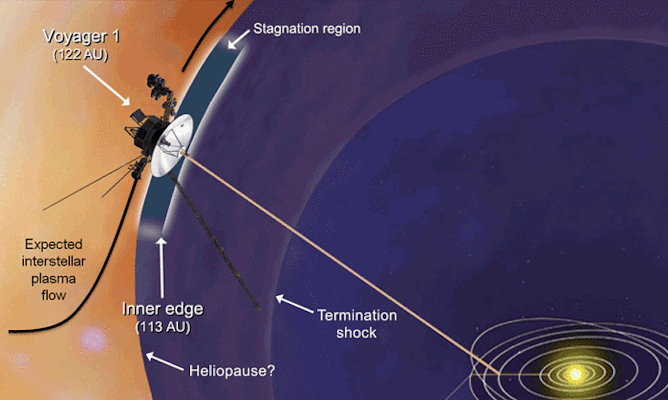
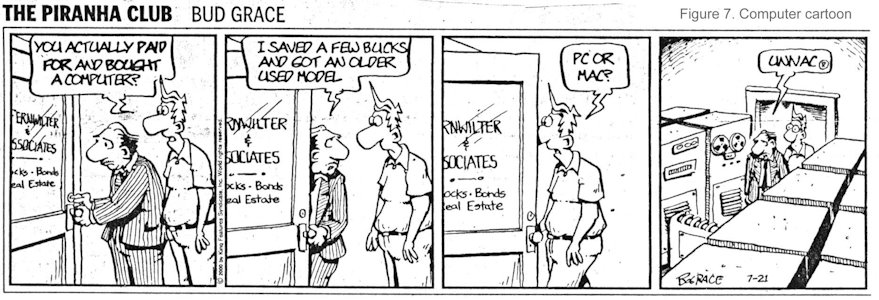
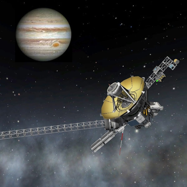
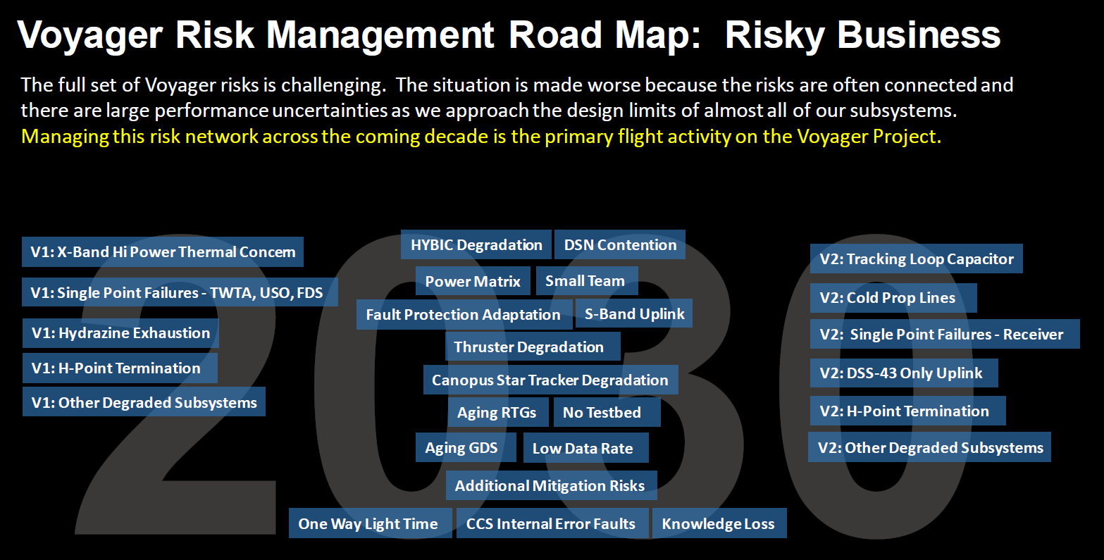
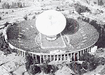
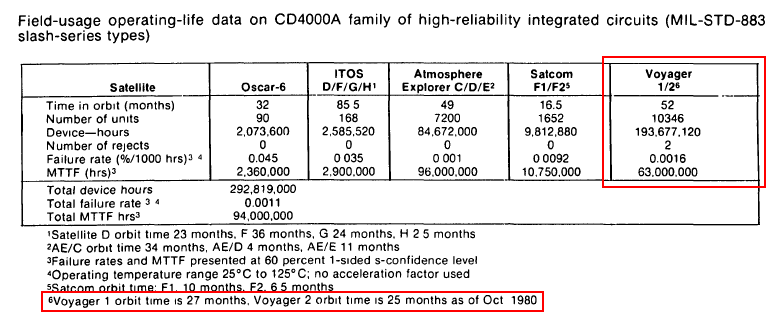
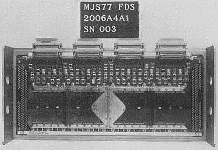
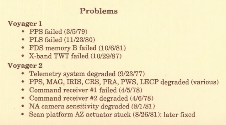
![[Magazine cover]](datamation-July-1983.jpg)